
New light guide plate

A light guide plate, a new type of technology, applied in the field of light guide plates, can solve the problems of insufficient brightness of the light guide plate, low light utilization rate of the light guide plate, etc., to achieve the effect of improving the light energy utilization rate, increasing the brightness, and improving the uniformity of light output

Inactive Publication Date: 2019-11-08
DONGGUAN YUANLI ELECTRONICS TECH
View PDF5 Cites 0 Cited by
  • Summary
  • Abstract
  • Description
  • Claims
  • Application Information

AI Technical Summary

Problems solved by technology

[0004] However, it is easy to have the problem of low light utilization rate of the light guide plate by simply guiding the light to be emitted from the light-emitting surface through the light guide point, which leads to the problem of insufficient brightness of the light guide plate.

Method used


Image

  • New light guide plate
  • New light guide plate
  • New light guide plate

Examples


Embodiment Construction

[0031] The present invention will be described in detail below in conjunction with the accompanying drawings and embodiments.

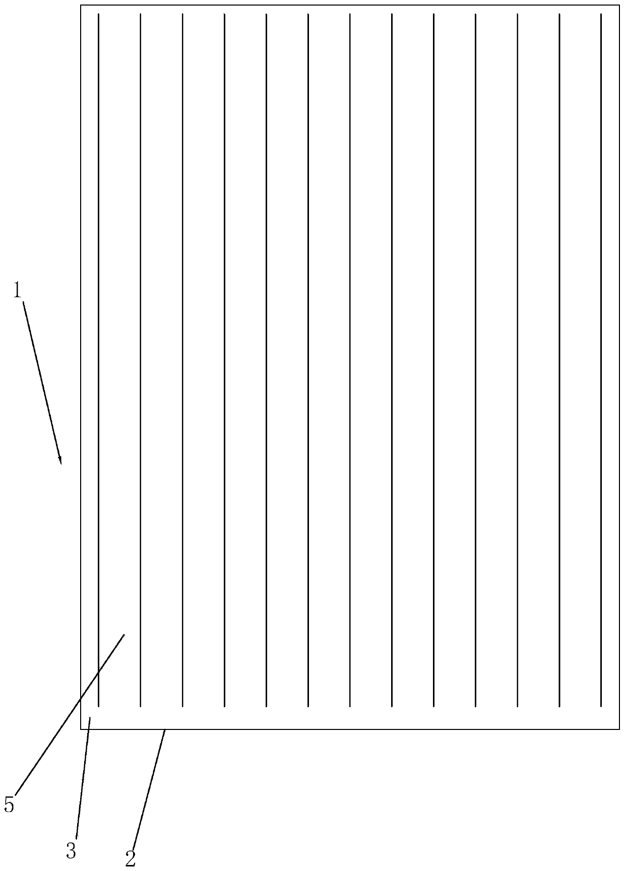
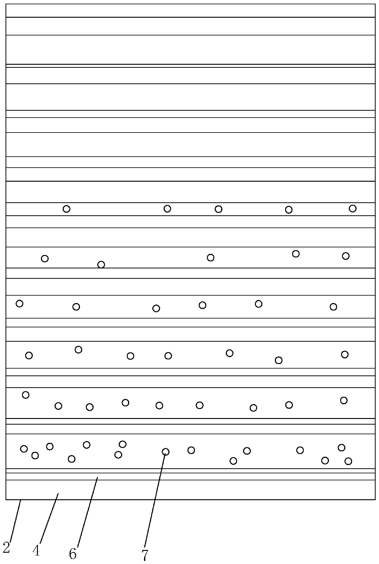
[0032] A new type of light guide plate, such as figure 1 with image 3 As shown, it includes a flat light guide plate body 1, and the light guide plate body 1 is made of polycarbonate, polymethyl methacrylate or acrylic synthetic resin material. One side wall of the light guide plate body 1 is the light incident surface 2 , and the two opposite surfaces of the light guide plate body 1 are the light output surface 3 and the reflection surface 4 respectively.

[0033] Such as figure 1 with figure 2 As shown, the surface of the light-emitting surface 3 has circular-arc convex structures 5 that are regularly and continuously arranged, and the refraction angle of the light can be changed through the circular-arc convex structures 5 on the light-emitting surface 3, so as to achieve the effect of concentrating light, and then make the light use reasonabl...


PUM


Abstract

The invention relates to the technical filed of light guide plates, in particularly to a new light guide plate. The key technical solution thereof is that the new light guide plate comprises a light guide plate body, wherein one side wall of the light guide plate body is a light incident surface, two opposite surfaces of the light guide plate body are respectively a light exiting surface and a reflecting surface, the reflecting surface has a plurality of V-shaped structures arranged in equal distance, the vertex angles of the plurality of V-shaped structures are invariable and the depth gradually increases towards the direction away from the light incident surface, compensating guiding spots are distributed on the reflecting surfaces of two adjacent V-shaped structures, the density of thecompensating guiding spots gradually decreases towards the direction away from the light guide plate body to the light incident surface, the light incident surface has circular arc convex structures regularly and continuously arranged, and the circular arc convex structures and the V-shaped structures are vertically arranged. The new light guide plate provided by the invention has the advantages of improving efficiency for solar energy utilization of light incidence of the light guide plate.

Description

technical field [0001] The invention relates to the technical field of light guide plates, more specifically, it relates to a novel light guide plate. Background technique [0002] The light guide plate generally includes a light incident surface, a light exit surface connected to the light incident surface, and a reflective surface opposite to the light exit surface. In the side-illuminated light source module, the light emitted by the light-emitting elements (such as LED lamps) arranged on the side of the light guide plate (that is, the light incident surface) is mainly guided to the front of the light guide plate through the reflective surface. (that is, the light-emitting surface) to form a surface light source. [0003] In order to make the light emit from the light-emitting surface to form a uniform surface light source, light-guiding points (miniature protrusions or depressions distributed in a net shape) are usually distributed on the reflecting surface. When the li...

Claims


Application Information

Patent Timeline
Patent Type & Authority Applications(China)
IPC IPC(8): G02B6/00
CPCG02B6/0038G02B6/004G02B6/0058
Inventor 黄爱群阮绪红
Owner DONGGUAN YUANLI ELECTRONICS TECH
Learn More