
Method for predicting transverse wave time difference by using logging data

A technology of shear wave time difference and logging data, which is applied in the field of prediction of shear wave time difference, can solve the problems of increasing the multiplicity and error of calculation results, large amount of calculation, and large error of prediction results, etc., to save exploration cost, good effect, and algorithm simple effect

Inactive Publication Date: 2019-11-08
PETROCHINA CO LTD
View PDF3 Cites 8 Cited by
  • Summary
  • Abstract
  • Description
  • Claims
  • Application Information

AI Technical Summary

Problems solved by technology

[0005] (1) Since the parameters that need to be input in the empirical formula method include density, P-wave transit time, resistivity, etc., it can only be applied in key wells
In most development wells or old wells, only compressional wave transit time and resistivity curves are measured, but density measurement is not performed, which makes it unable to be widely used
At the same time, in the gas layer section, since the compressional wave time difference and density are affected by the gas in the reservoir, the shear wave time difference predicted by using it is also affected by the gas layer, and the prediction results have large errors and cannot be used
[0006] (2) The Xu-White theoretical model method requires many input parameters, and most of the parameters are difficult to obtain directly, and need to be calculated from other data
It leads to a large amount of calculation, low calculation efficiency, and more calculation processes increase the multi-solution and error of the calculation results

Method used


Image

  • Method for predicting transverse wave time difference by using logging data
  • Method for predicting transverse wave time difference by using logging data
  • Method for predicting transverse wave time difference by using logging data

Examples


Embodiment 1

[0073] The present invention takes the Triassic Chang 8 reservoir in the Pengyang area in the west of the Ordos Basin as an example, and the specific implementation methods are as follows:

[0074] see figure 1 , a method for predicting shear time difference using conventional logging data, the following steps are carried out:

[0075] Step 1. Since in all exploratory wells in this area, the acoustic time difference measured by conventional logging instruments is in metric units, so first use the formula DT=DT G / 3.281 converts the measured sonic time difference into sonic time difference in imperial units.

[0076] Step 2. Combining oil testing and test data, select 3 wells that are tested as oil layers and 2 wells that are tested as water layers, and use the formula Calculate the shear wave time difference.

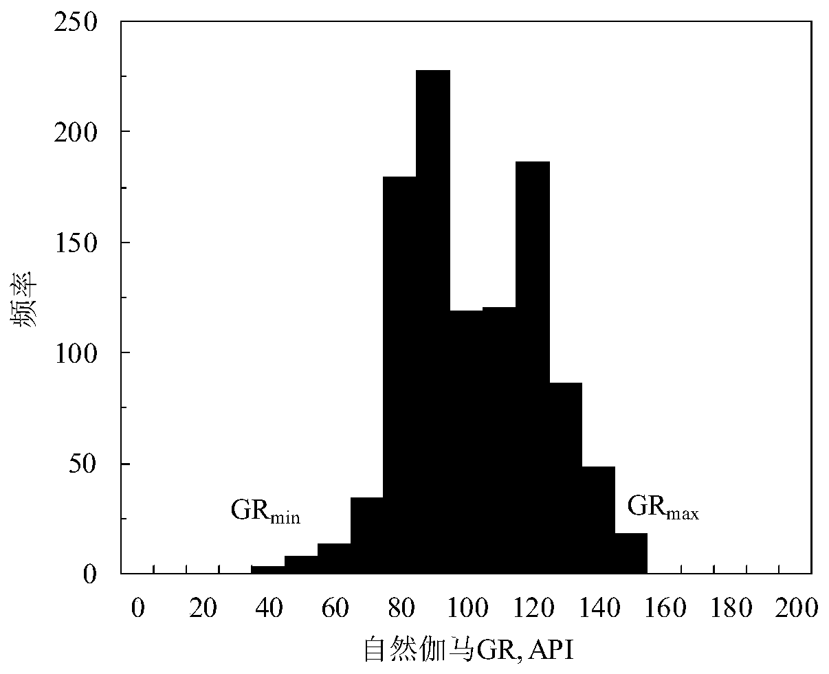
[0077] Step 3. In the same interval as the above-mentioned test interval, read the natural gamma ray logging value, and make a statistical histogram of the natural ...


PUM


Abstract

The invention discloses a method for predicting the transverse wave time difference by using logging data, and belongs to the technical field of petroleum logging. According to the method, a transverse wave time difference curve is constructed by using longitudinal wave time difference and density in an oil layer and / or a water layer section, a natural gamma relative value is calculated out by using natural gamma logging, and then a relevant relationship between the natural gamma relative value and the transverse wave time difference is established. A formula for predicting the transverse wavetime difference is established by using conventional logging data, so that accurate acquisition of the transverse wave time difference in any stratum (including oil, gas and water layers) is realized, the transverse-to-longitudinal wave time difference ratio and the Poisson's ratio which reflect properties of a reservoir fluid and parameters such as the Young's modulus, the bulk modulus and the shear modulus which reflect mechanical properties of a reservoir rock are calculated by using the transverse wave time difference, and the purposes of effectively identifying the gas layer and quantitatively evaluating the mechanical properties of the reservoir rock are further achieved.

Description

technical field [0001] The invention belongs to the technical field of petroleum well logging, in particular to a method for predicting shear wave time difference by using well logging data. Background technique [0002] A transverse wave is a wave whose direction of propagation is perpendicular to the vibration direction of the particle. Shear wave time difference is an important parameter for reservoir lithology, fluid identification and calculation of rock mechanics parameters, especially in the division of gas and oil (water) layers and calculation of rock mechanics parameters, the role of compressional and shear wave time difference is particularly important . According to the P-wave and S-wave time differences, parameters such as the S-wave time difference ratio, Poisson's ratio, and volume compressibility coefficient reflecting the difference in reservoir fluid properties (mainly gas and oil (water)) can be calculated. At the same time, parameters such as Young's mo...

Claims


Application Information

Patent Timeline
Patent Type & Authority Applications(China)
IPC IPC(8): G01V11/00
CPCG01V11/00
Inventor 石玉江郭浩鹏李高仁周金昱王长胜张海涛李卫兵张少华钟吉彬郭清娅刘红升张丛秀
Owner PETROCHINA CO LTD
Learn More