
A method for detecting the wear condition of an automobile continuously variable transmission

A technology of continuously variable transmission and detection method, which is applied to instruments, measuring devices, scientific instruments, etc., can solve the problem of affecting the establishment of lubricating oil film on the surface of friction pairs, affecting the service life of metal belts and pulleys in CVT, and affecting CVT power transmission. efficiency and other issues, to achieve the effect of low cost, uniform size and good fluorescence performance

Active Publication Date: 2022-04-08
JILIN UNIV
View PDF7 Cites 0 Cited by
  • Summary
  • Abstract
  • Description
  • Claims
  • Application Information

AI Technical Summary

Problems solved by technology

Metal belt CVT has smoother shifting and higher fuel efficiency than traditional transmissions, but on the other hand, due to the steel-steel friction pair formed between the metal belt and the pulley, it will be affected by temperature, load The combined action of factors such as the friction plate often causes the wear of the metal belt, especially the friction plate.
On the one hand, wear will lead to the loss of the surface of the friction plate and the pulley, which will affect the service life of the metal belt and pulley in the CVT. power transfer efficiency

Method used

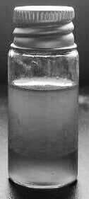
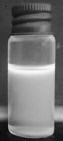
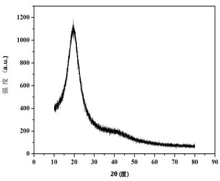

Image

  • A method for detecting the wear condition of an automobile continuously variable transmission
  • A method for detecting the wear condition of an automobile continuously variable transmission
  • A method for detecting the wear condition of an automobile continuously variable transmission

Examples


specific Embodiment approach 1

[0031] Specific embodiment one: the preparation method of fluorescent nanosensor in this embodiment is characterized in that the method comprises the following steps:

[0032] 1. Weigh 0.5g of EDTA, add 2ml of nitric acid with a concentration of 0.5mol / L (the purpose is to dissolve EDTA), then add 4ml of oleic acid and 10ml of octadecene, and mix ultrasonically at room temperature to form a uniform mixed solution;

[0033] 2. Put the mixed solution obtained in step 1 into a high-temperature reactor, and then put the reactor into an oven for 10 hours;

[0034] 3. Set the solution obtained in step 2 as A, take 15ml of solution A, pour 2 times the volume of methanol (for purification), and then perform centrifugation, and take the supernatant after standing still, which is solution B;

[0035] 4. Put the solution B obtained in step 3 under purple light to irradiate, showing blue light;

[0036] 5. Collect the same amount of lubricating oil used in five sets of CVTs of the same m...

specific Embodiment approach 2

[0038] Embodiment 2: This embodiment differs from Embodiment 1 in that: the power of the ultrasonic mixing in Step 1 is 60-80W. Others are the same as in the first embodiment.

specific Embodiment approach 3

[0039] Embodiment 3: The difference between this embodiment and Embodiment 1 or 2 is that the reaction temperature in step 2 is 200°C. Others are the same as in the first or second embodiment.


PUM

PropertyMeasurementUnit
sizeaaaaaaaaaa

Abstract

The invention discloses a preparation method and application of a fluorescent nanometer sensor to detect the wear condition of the metal belt of the existing automobile continuously variable transmission. In the experiment, ethylenediaminetetraacetic acid was used as carbon source, and fluorescent carbon quantum dots were prepared by hydrothermal method. Collect the same amount of lubricating oil used in five groups of automotive continuously variable transmissions with different mileages of the same model, mix them with the same amount of silicone oil, and number 1-5 after mixing evenly. The prepared fluorescent carbon quantum dots were divided into five equal parts, mixed with solution 1-5 respectively, and irradiated under purple light to observe the fluorescence. The wear condition of the metal belt of the continuously variable transmission of the automobile is detected by the degree of fluorescence quenching of the mixture. The invention has low cost and high detection sensitivity, and plays an important role in the early failure diagnosis of the continuously variable transmission of the automobile.

Description

technical field [0001] The invention relates to a preparation method and application of a nanometer sensor. Background technique [0002] The development history of automotive continuously variable transmission has been more than 100 years, but the metal belt continuously variable transmission has only developed rapidly in the last ten years. Metal belt CVT has smoother shifting and higher fuel efficiency than traditional transmissions, but on the other hand, due to the steel-steel friction pair formed between the metal belt and the pulley, it will be affected by temperature, load The joint effect of factors such as friction often causes the wear of the metal belt, especially the friction plate. On the one hand, wear will lead to the loss of the surface of the friction plate and the pulley, which will affect the service life of the metal belt and pulley in the CVT. power transfer efficiency. Therefore, the lubricating oil used by the CVT will be mixed with metal debris du...

Claims


Application Information

Patent Timeline
Patent Type & Authority Patents(China)
IPC IPC(8): G01N21/64
CPCG01N21/6402
Inventor 韩玲任磊磊刘鸿祥
Owner JILIN UNIV
Learn More