
Long-distance light-sensing measurement and analysis device

A measurement analysis, long-distance technology, applied in the field of long-distance detection, can solve the problems of display target resolution error, detection result deviation, low resolution, etc., and achieve the effect of clear dividing line, easy operation and high resolution

Active Publication Date: 2019-11-08
WUCHANG UNIV OF TECH
View PDF18 Cites 0 Cited by
  • Summary
  • Abstract
  • Description
  • Claims
  • Application Information

AI Technical Summary

Problems solved by technology

[0004] However, because the UAV or satellite is too far away from the target, the detection accuracy of the precise target is not enough, and due to the large difference in the light in the air and the angle difference of the reflected light of the target, the boundary line of the precise target detection is unclear, or the detection of the precise target is unclear. The light display of the detection target is abnormal, ranging from a low resolution to a serious error of display target resolution, resulting in large deviations in detection results

Method used


Image

  • Long-distance light-sensing measurement and analysis device
  • Long-distance light-sensing measurement and analysis device

Examples


Embodiment 1

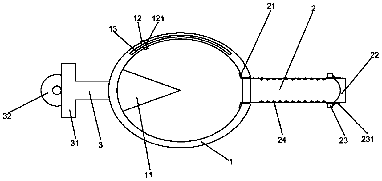
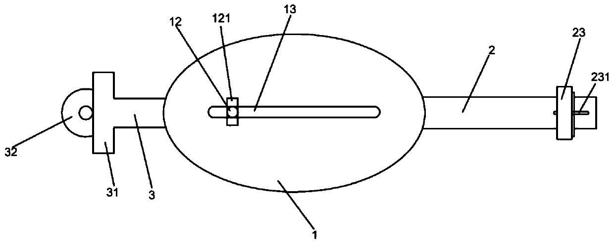
[0025] Embodiment one: if figure 1 As shown, it is only one of the embodiments of the present invention, a long-distance photosensitive measurement and analysis device, including a functional ball 1, a lighting tube 2 arranged on the functional ball 1, and a lighting tube 2 arranged on the functional ball 1 away from the The control rod 3 on one side of the lighting tube 2, the lighting tube 2 and the control rod 3 are coaxially arranged and the axes of the lighting tube 2 and the control rod 3 pass through the center of the functional ball 1, and the inner wall of the functional ball 1 A reflective coating is provided, a refracting mirror 11 is provided inside the functional ball 1, an observation lens 12 is provided on the functional ball 1, a chute 13 for facilitating the sliding of the observation lens 12 is provided on the functional ball 1, The end of the control rod 3 is provided with a driving machine 31 for driving the control rod 3 to rotate around the axis of the co...

Embodiment 2

[0033] Embodiment two, still as figure 1 As shown, it is still one of the embodiments of the present invention. In order to make a long-distance photosensitive measurement and analysis device of the present invention more practical and stable, and the detection effect is good, the present invention also has the following designs:

[0034] First, the end of the daylighting tube 2 close to the functional ball 1 is provided with a stop buckle 21 . It is convenient to connect and fix the lighting tube 2 and the functional ball 1. When the control rod 3 rotates, there will be no relative displacement between the lighting tube 2 and the functional ball 1, so as to avoid blocking the target detection object.

[0035] Then, the lighting tube 2 is a cylinder, so when the lighting tube 2 rotates around its axis, the detection target remains unchanged.

[0036] Also, the inner wall of the daylighting tube 2 is provided with a light-absorbing coating 24 . Avoid light rays with an excess...


PUM


Abstract

The invention, which relates to the technical field of medical appliances, provides a long-distance light-sensing measurement and analysis device comprising a functional ball, a lighting tube disposedon the functional ball, and a control rod disposed at one side, away from the lighting tube, of the functional ball. The lighting tube and the control rod are arranged coaxially and axes of the lighting tube and the control rod passes through the center of the functional ball. A reflective coating is arranged on the inner wall of the function ball; a refractor is arranged in the function ball; anobservation lens is arranged at the function ball; and a chute for observing the sliding of the lens is formed in the function ball. A driving machine for driving the control rod to rotate around theaxis of the control rod is arranged at the end portion of the control rod. The long-distance light-sensing measurement and analysis device having a simple structure is used conveniently. With light offset, a target is detected at multiple angles to obtain accurate target information; the resolution is high; the boundary line is obvious; and the long-distance light-sensing measurement and analysisdevice can be carried on a high-altitude detector to detect and analyze a long-distance ground target accurately.

Description

technical field [0001] The invention relates to the field of remote detection technology, [0002] In particular, the present invention relates to a remote light sensing measurement analysis device. Background technique [0003] With the development of remote sensing technology, high spatial resolution remote sensing images have become the main data source for applications such as precision agriculture, target recognition, disaster assessment, and change monitoring. In practical applications, surveying and mapping devices are required to scan the target terrain to obtain target terrain information. UAVs or synchronous satellites are generally used for high-altitude detection, especially UAVs are the most widely used. [0004] However, because the UAV or satellite is too far away from the target, the detection accuracy of the precise target is not enough, and due to the large difference in the light in the air and the angle difference of the reflected light of the target, th...

Claims


Application Information

Patent Timeline
Patent Type & Authority Applications(China)
IPC IPC(8): G01N21/47G01N21/01
CPCG01N21/47G01N21/01
Inventor 安庆柳立生欧阳玉华王金玲
Owner WUCHANG UNIV OF TECH
Learn More