
Energy storage type industrial hot air blower

A hot air blower, industrial technology, applied in heat storage heaters, fluid heaters, lighting and heating equipment, etc., can solve problems such as damage to instruments and meters, great influence on the accuracy of temperature control, and lagging sensor temperature detection , to achieve the effect of low cost, simple structure and strong practicability

Pending Publication Date: 2019-11-08
珠海保能绿色能源科技有限公司
View PDF6 Cites 2 Cited by
  • Summary
  • Abstract
  • Description
  • Claims
  • Application Information

AI Technical Summary

Problems solved by technology

However, the sensor has the disadvantage of temperature detection hysteresis, that is, the actual temperature field has reached the temperature set by the system, but because the sensor has not detected it, the actuator continues to work, which causes the temperature field temperature to deviate from the set temperature within the lag time. Fixed value is getting bigger and bigger
[0005] (2) Some components of the temperature control system work in a relatively high ambient temperature, which will not only cause certain damage to the instruments and meters of the system, but also have a greater impact on the accuracy of temperature control, especially for the use of thermocouples for measurement. temperature sensor systems have a greater impact on the
[0006] (3) For the convenience of installation or the convenience of users using the temperature field, the temperature measurement sensors are mostly installed at the corners of the temperature field. For the uneven system with large temperature field, many openings or no circulation device, the temperature measurement sensor is used as the temperature measurement point Likely not representative to accurately reflect temperature conditions

Method used


Image

  • Energy storage type industrial hot air blower
  • Energy storage type industrial hot air blower
  • Energy storage type industrial hot air blower

Examples


Embodiment 1

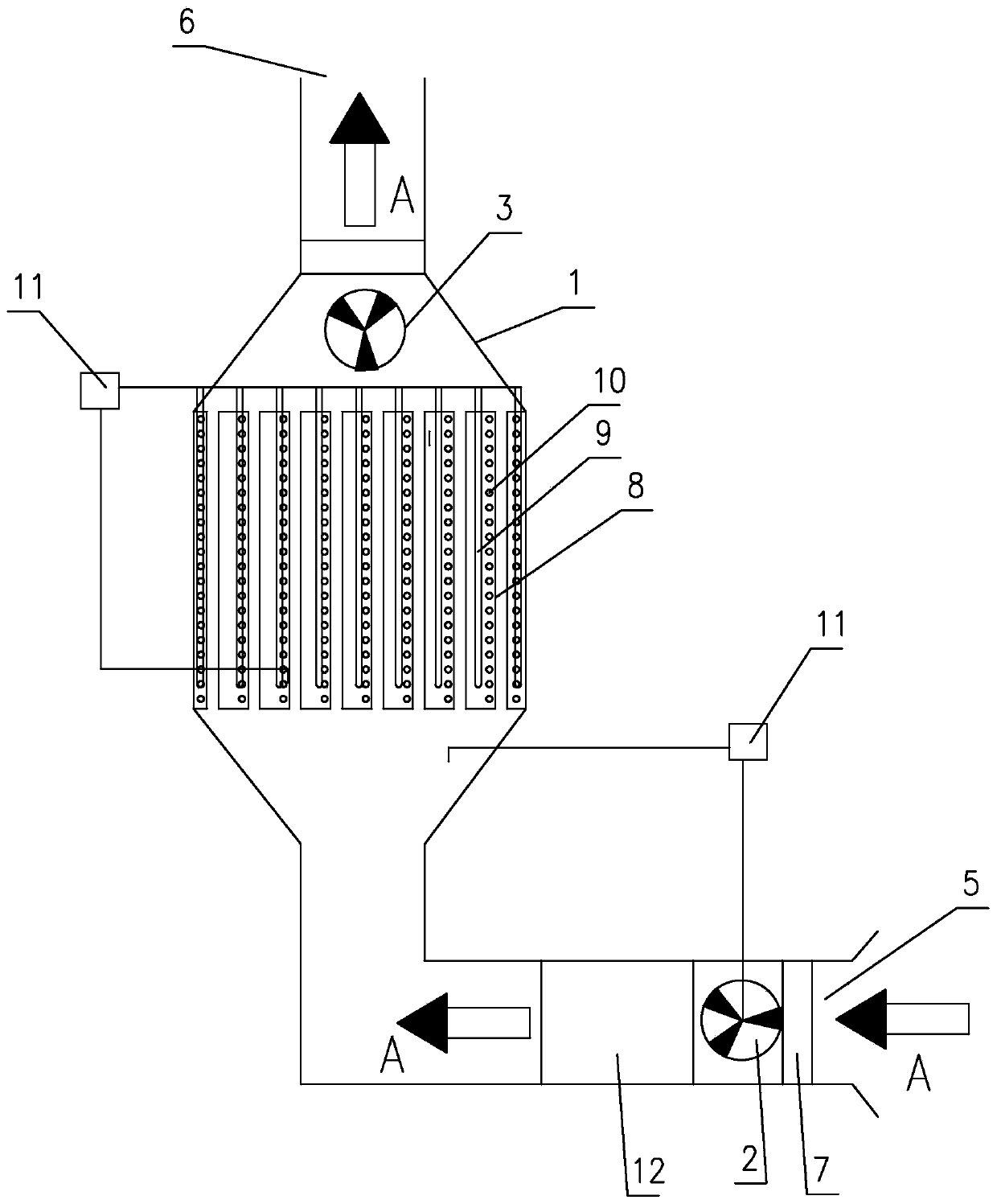
[0030] Such as figure 1 As shown, it is an energy storage type industrial hot air blower of the present invention, which includes a temperature control system, a casing 1, a first fan 2 arranged in the casing 1, a second fan 3, a heater 4, a condenser 7 and The heat storage device, the casing 1 has an air inlet 5 and an air outlet 6, the first fan 2 is arranged at the air inlet 5, and the second fan 3 is arranged in front of the heat storage device, that is, between the heat storage device and the air outlet 6. The heater adopts an electric heater, and the electric heater is located in front of the first fan 2, while the heat storage device is located in front of the electric heater, and the condenser 7 is used to condense and dry the cold air A, and it is located in the air inlet 5 And it is located behind the first fan 2 . The heat storage device includes a heat source, a casing and a heat storage material 10 filled in the casing. The maximum temperature of the phase transi...

Embodiment 2

[0036] Such as figure 2 As shown, the difference between this embodiment and Embodiment 1 is that the heater adopts the biomass oil furnace heater 12 .

[0037]The working process of this embodiment is: the cold air enters from the air inlet, passes through the condenser to condense and dry, and then is pumped by the fan to pass through the heater to heat the air. The heater is a biomass oil furnace heater, and the flame can be adjusted to at least three levels. . If the temperature exceeds the target temperature before entering the heat storage device, reduce the flame level. The heated hot air passes through the heat storage device and is reheated by the heat storage material. The electric heating tube of the heat storage device controls the temperature of the heat storage material to be in a quasi-constant temperature zone. The temperature of the hot air at the air outlet is determined and regulated by the temperature of the heat storage material and the speed of the fan...

Embodiment 3

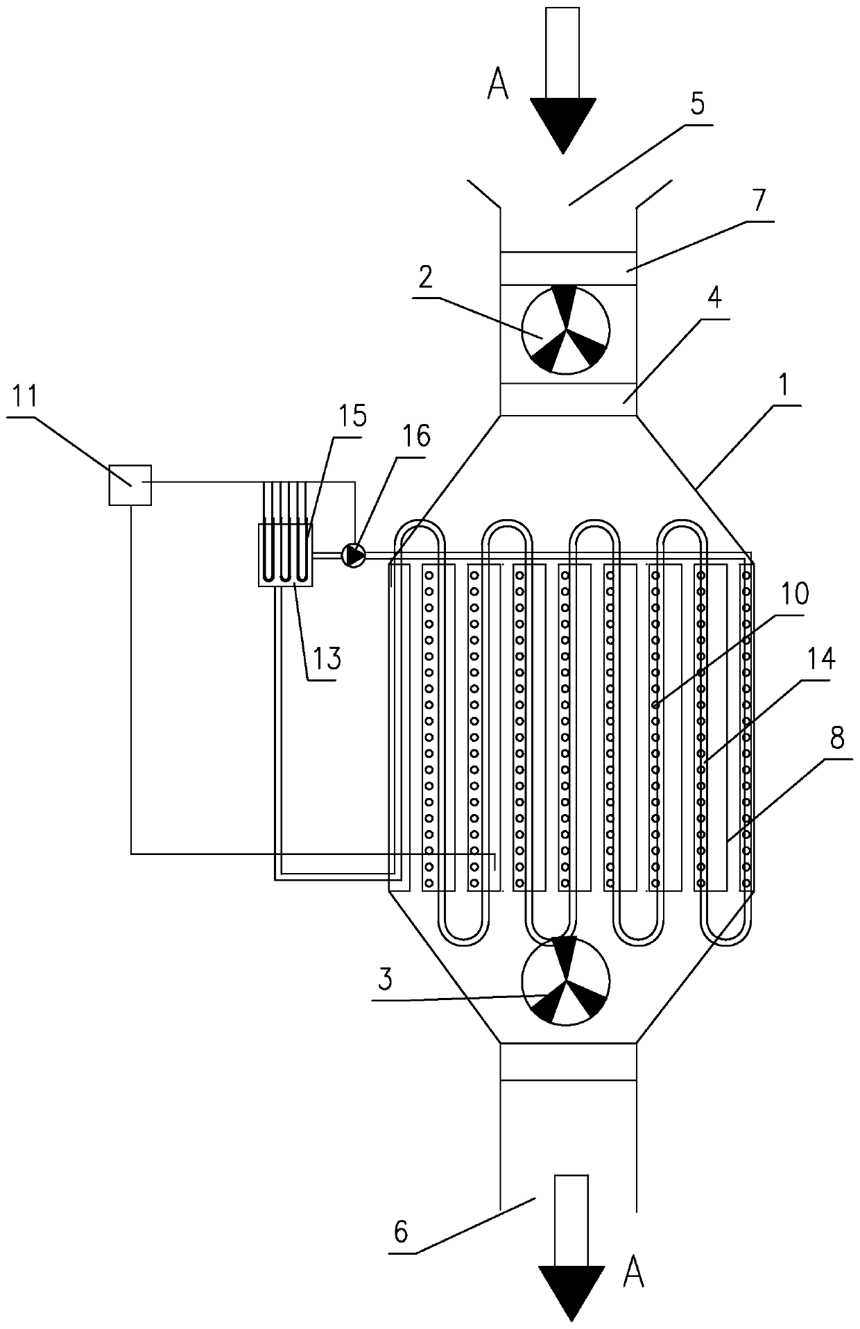
[0039] Such as image 3 As shown, the difference between this embodiment and Embodiment 1 is that the heat source is mainly composed of an oil tank 13 and a heating pipe 14. It is a serpentine tube, and the shell of the heat storage device is a plurality of tube bodies 8 arranged side by side and connected as a whole. The outer edge of the shell is connected with the inner wall of the casing. The heat storage material 10 is in contact. The heat conduction oil in the oil tank 13 is heated by the electric heating tube 15, and the controller 11 is connected with the electric heating tube 15 and the circulation pump 16 on the circulation circuit respectively, and is used to control the start and stop of the electric heating tube 15 and the circulation pump 16.


PUM


Abstract

The invention discloses an energy storage type industrial hot air blower. The energy storage type industrial hot air blower comprises a temperature control system, a machine shell, a first fan arranged in the machine shell, a heater and a heat storage device, wherein the shell is provided with an air inlet and an air outlet, the first fan is arranged in the air inlet, the heater is positioned in front of the first fan, the heat storage device is positioned in front of the heater, the heat storage device comprises a heat source, a shell and a heat storage material filling the shell, the heat source exchanges heat with the heat storage material to heat the heat storage material and store the heat, and cold air entering from the air inlet is heated through the heater and then is heated through the heat storage material so as to control the temperature of hot air at the air outlet. According to the energy storage type industrial hot air blower, the heat storage material is used for heatingthe heated air again, the temperature of the heat storage material is in the quasi-constant temperature zone based on the characteristic of the phase change temperature of the heat storage material,the temperature of the hot air at the air outlet is determined and controlled by means of the temperature of the heat storage material and the speed of the fans, and the target temperature can be corrected again; and on the basis of the heat storage characteristic of the heat storage material, the energy storage type industrial hot air blower has the energy-saving and energy-storage effects.

Description

technical field [0001] The invention relates to an industrial hot air blower, in particular to an energy storage type industrial hot air blower. Background technique [0002] Industrial hot air blowers are generally composed of fans, heaters and temperature control systems. Among them, the heater of the gas-fired industrial hot air blower is a gas burner, which is installed in the combustion chamber, and the cold air is heated by the burner combustion, and the hot air is formed by the rotation of the fan and sent out from the air outlet. The heater of the electric fan is an electric heater. The cold air is sent in by the fan from the air inlet, and heated by the electric heater to form hot air and sent out from the air outlet. The electric heater fan controls the power of the electric heater and the speed of the fan according to the temperature of the air outlet to achieve temperature regulation. [0003] But there are following defects in existing industrial hot air blowe...

Claims


Application Information

Patent Timeline
Patent Type & Authority Applications(China)
IPC IPC(8): F24H7/04F24H9/18F24H9/20
CPCF24H7/0416F24H9/1863F24H9/2078
Inventor 寇翠青柳一泽柳一曼
Owner 珠海保能绿色能源科技有限公司
Learn More