STF-based anti-shock sliding shock isolator

A vibration isolator and sliding technology, which is applied to bridge parts, bridges, buildings, etc., can solve the problems of limited energy consumption, lack of anti-shock and vibration reduction, and difficult control of the horizontal displacement of the vibration-isolation support. Good anti-shock effect

Active Publication Date: 2019-11-08
JIANGSU HONGJI ENERGY SAVING NEW TECH CO LTD
View PDF9 Cites 0 Cited by
  • Summary
  • Abstract
  • Description
  • Claims
  • Application Information

AI Technical Summary

Problems solved by technology

[0005] Chinese patent (application number: 201520641719.3) discloses the "elastic sliding shock-isolation bearing" by setting the sliding plate so that the horizontal stiffness is zero under the condition that the horizontal force is greater than the frictional force, which extends the life of the vibration-isolation bearing. Natural vibration period, but does not have the function of anti-shock energy dissipation
Chinese patent (application number: 201621169902.9) discloses "shock-isolation bearing with multi-stage self-resetting ability" through high damping rubber bearing and friction sliding bearing in series, combining the advantages of both to improve the performance of the vibration-isolation bearing Reset ability, but the horizontal displacement of the isolation support is not easy to control, and the energy dissipation capacity is limited during the isolation process
[0006] Aiming at the technical problems existing in the prior art, the present invention proposes a shock-resistant sliding shock isolator based on STF, which overcomes the shortcomings of traditional sliding bearings with limited energy consumption and lack of shock-resistance and vibration-reduction effects

Method used


Image

  • STF-based anti-shock sliding shock isolator
  • STF-based anti-shock sliding shock isolator
  • STF-based anti-shock sliding shock isolator

Examples


Embodiment

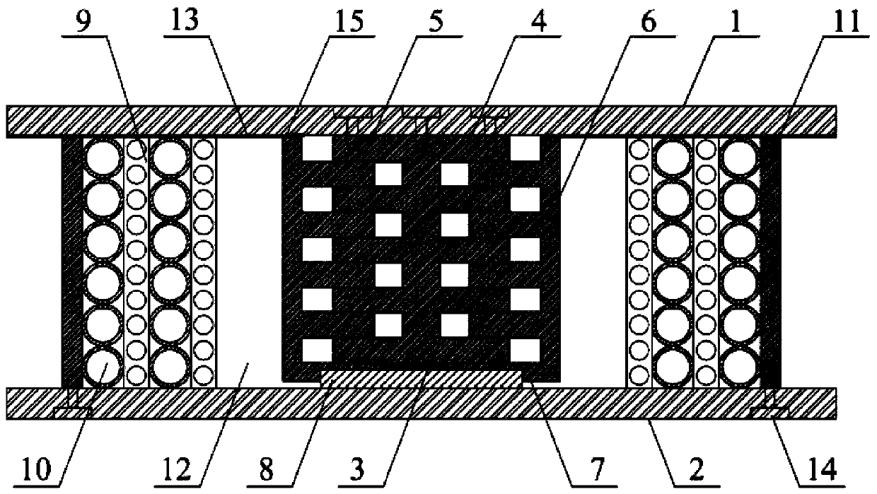
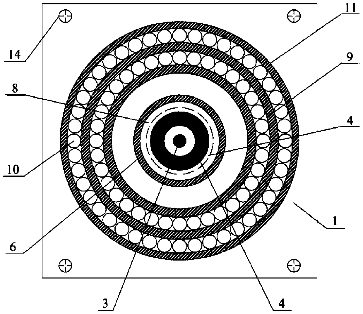
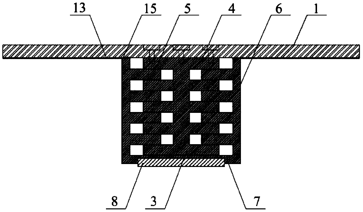
[0023] Example: see Figure 1-3 , the present invention provides a technical solution: a STF-based impact-slip shock isolator, which includes an upper cover plate 1, a lower bearing platform plate 2, a solid cylinder 3, a steel plate column 4, a sleeve 6, and a rubber plate 8 and sleeve two 11, the upper end of the sleeve two 11 is placed with the upper cover plate 1, the lower end of the sleeve two 11 is fixedly connected with the lower platform plate 2 through bolts 14, the cavity of the sleeve two 11 A solid cylinder 3 is also coaxially arranged inside the body, and the solid cylinder 3 is fixedly connected with the upper cover plate 1 through bolts 14. The outer coaxial sleeve of the solid cylinder 3 is provided with a sleeve one 6, and the solid cylinder 3 and the upper cover plate 1 are fixedly connected. Sleeve one 6 is respectively welded with steel plate column 4 along its vertical direction, and the bottom of described sleeve one 6 is welded with connection plate 7, ...


PUM


Abstract

The invention discloses an STF-based anti-shock sliding shock isolator which comprises an upper cover plate, a solid cylinder, a first sleeve, a steel plate column, a rubber layer, a connecting plate,a honeycomb sleeve, a second sleeve, a shear thickening cavity, a high-damping rubber ball, a rubber plate, a lower bearing sheet and a bolt. The solid cylinder, the first sleeve, the steel plate column, the connecting plate and the shear thickening cavity jointly form a sliding support; the honeycomb sleeve, the high damping rubber ball and the shear thickening cavity form an anti-shock energy dissipation part; in order to solve the problem that a conventional sliding support is limited in energy-dissipating capacity, large in slippage amount and lack of anti-shock effects, dynamic frictionenergy consumption between a steel plate and rubber is used; and the shear thickening cavity is designed, so that the device can provide greater damping force and dissipate impact energy under high-speed impact loads.

Description

technical field [0001] The invention belongs to the technical field of bridge shock isolation, and in particular relates to an STF-based anti-shock and sliding shock isolator. Background technique [0002] my country is a country with frequent earthquakes. Frequent earthquakes not only cause serious damage to structures, but also bring harm to our living environment that cannot be ignored. Traditional anti-seismic structures resist earthquakes by enhancing structural strength. Structural components enter an inelastic state during an earthquake, have a certain degree of ductility, and consume seismic energy at the cost of damage to the structure itself, thereby reducing the seismic response. [0003] In recent years, a variety of shock isolation and vibration reduction methods have emerged as the times require, and they are effective in application. For example, traditional sliding bearings can reduce the horizontal acceleration response of the structure by reducing the horiz...

Claims


Application Information

Patent Timeline
Patent Type & Authority Applications(China)
IPC IPC(8): E01D19/04
CPCE01D19/041
Inventor 苑举卫卫海
Owner JIANGSU HONGJI ENERGY SAVING NEW TECH CO LTD
Why Eureka
Try Eureka