Residual current mutual inductor and assembling technology thereof

A residual current and assembly process technology, applied in the field of transformers, can solve the problems of transformer performance degradation, performance degradation, and complicated installation, and achieve the effect of convenient later transformation.

Inactive Publication Date: 2019-11-05
JIANGYIN SPARK ELECTRONICS TECH
View PDF0 Cites 1 Cited by
  • Summary
  • Abstract
  • Description
  • Claims
  • Application Information

AI Technical Summary

Problems solved by technology

[0003] During the implementation and use, it was found that the conventional residual current transformer has the following disadvantages: ①The open-close structure is tightened by screws, which leads to cumbersome installation; ②The high and low temperature characteristics of the conventional residual current transformer cannot meet the requirements. The requirements are very strict, and its high and low temperature requirements are between -40°C and 75°C. Conventional residual current transformers are encapsulated with epoxy. In the environment, due to the inconsistency of the shrinkage rate of the epoxy and the iron core, the iron core is subjected to greater stress, thereby reducing its performance, and finally leading to a decline in the performance of the transformer; ③The conventional split residual current transformer is connected by screws, so the two Coils cannot be wound between the two halves at the same time, only one-sided winding can be used, resulting in poor balance characteristics

Method used


Image

  • Residual current mutual inductor and assembling technology thereof
  • Residual current mutual inductor and assembling technology thereof
  • Residual current mutual inductor and assembling technology thereof

Examples


Embodiment Construction

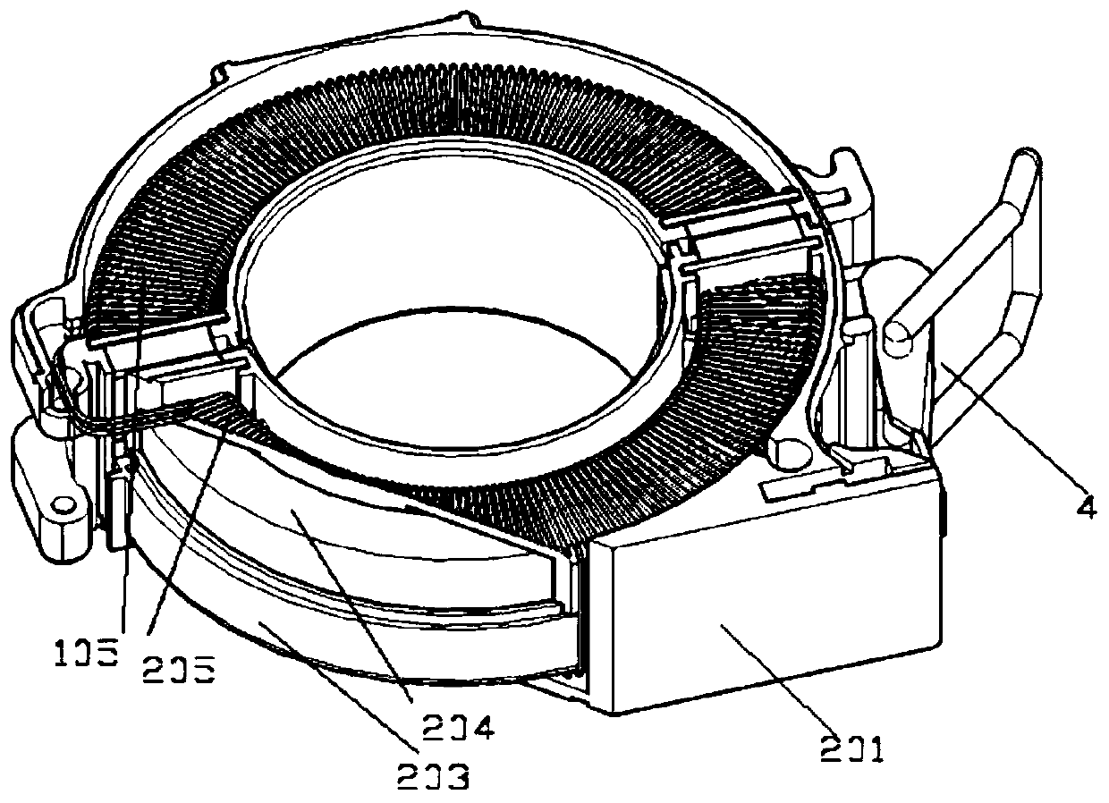
[0035] see Figure 1-19 , a residual current transformer related to the present invention, the residual current transformer includes an upper half ring 1 and a lower half ring 2, the left end of the upper half ring 1 and the left end of the lower half ring 2 are connected through a pin shaft 3 Hinged, the right end of the upper half ring 1 is connected with the right end of the lower half ring 2 through a buckle 4;

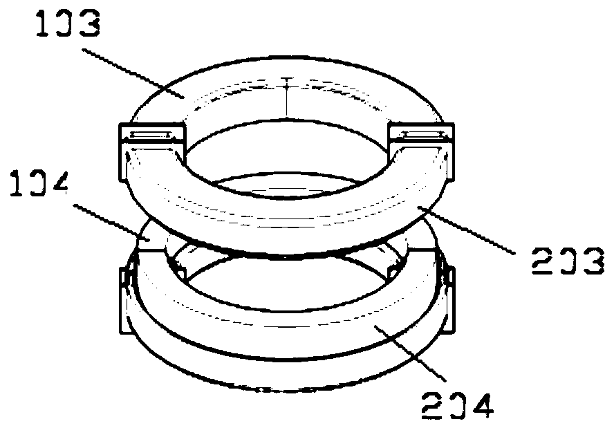
[0036] The upper half ring 1 includes an upper iron core assembly 102 installed in the upper casing 101, and the upper iron core assembly 102 includes an upper half iron core 104 installed in an upper frame 103, on which the upper frame 103 Wound with an upper winding group 105;

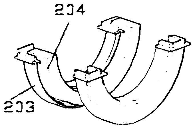
[0037] The lower half ring 2 includes a lower iron core assembly 202 installed in the lower casing 201, and the lower iron core assembly 202 includes a lower half iron core 204 installed in the lower frame 203, on which the lower frame 203 The lower winding group 105 is wound; and the ...


PUM


Abstract

The invention provides a residual current mutual inductor which comprises an upper half ring (1) and a lower half ring (2), wherein the left end of the upper half ring (1) and the left end of the lower half ring (2) are hinged through a hinge pin (3); the right end of the upper half ring (1) and the right end of the lower half ring (2) are connected through a hasp (4); and an upper winding group (105) and a lower winding group (106) are mutually connected. The residual current mutual inductor has the advantages of being convenient to install and use, good in product performance and good in measurement balance.

Description

technical field [0001] The invention relates to a residual current transformer and an assembly process thereof, belonging to the technical field of transformers. Background technique [0002] At present, the split-type residual current transformer dedicated to intelligent power consumption in the residual current transformer is also called the residual current sensor for fire monitoring. Its main function is to monitor, control and manage the circuit by sensing the residual current of the electrical circuit. Whether it is running normally, and send an alarm through the equipment to notify the operation and maintenance personnel in time, deal with abnormalities or faults, eliminate electrical fire hazards, and protect people's lives and property safety. [0003] During the implementation and use, it was found that the conventional residual current transformer has the following disadvantages: ①The open-close structure is tightened by screws, which leads to cumbersome installat...

Claims


Application Information

Patent Timeline
Patent Type & Authority Applications(China)
IPC IPC(8): H01F38/30H01F27/02H01F27/26H01F27/30H01F27/28H01F41/00H01F41/06G01R15/18
CPCG01R15/186H01F27/02H01F27/266H01F27/28H01F27/306H01F38/30H01F41/00H01F41/005H01F41/06H01F2038/305
Inventor 蒋大维朱慧吴垚顾伟杨有振袁芬蒋萍李果
Owner JIANGYIN SPARK ELECTRONICS TECH
Why Eureka
Try Eureka