
Tensor subspace continuous system identification method of bridge time-varying system

A time-varying system and continuous system technology, applied in special data processing applications, complex mathematical operations, instruments, etc., can solve problems such as inability to accurately reflect bridge modal information, difficulty in meeting bridge inspection requirements, and low computational efficiency.

Active Publication Date: 2019-11-05
SICHUAN DEPT OF TRANSPORTATION HIGHWAY PLANNING PROSPECTING & DESIGN RES INST
View PDF7 Cites 5 Cited by
  • Summary
  • Abstract
  • Description
  • Claims
  • Application Information

AI Technical Summary

Problems solved by technology

[0005] The purpose of the present invention is to overcome the existing subspace system identification method in the prior art when applied to the bridge time-varying system, the calculation efficiency is low, the identification result accuracy is low, the bridge modal information cannot be accurately reflected, and it is difficult to meet the requirements of bridge detection. Requirements and other issues, providing a tensor quantum space continuum system identification method for bridge time-varying systems

Method used


Image

  • Tensor subspace continuous system identification method of bridge time-varying system
  • Tensor subspace continuous system identification method of bridge time-varying system
  • Tensor subspace continuous system identification method of bridge time-varying system

Examples


Embodiment 1

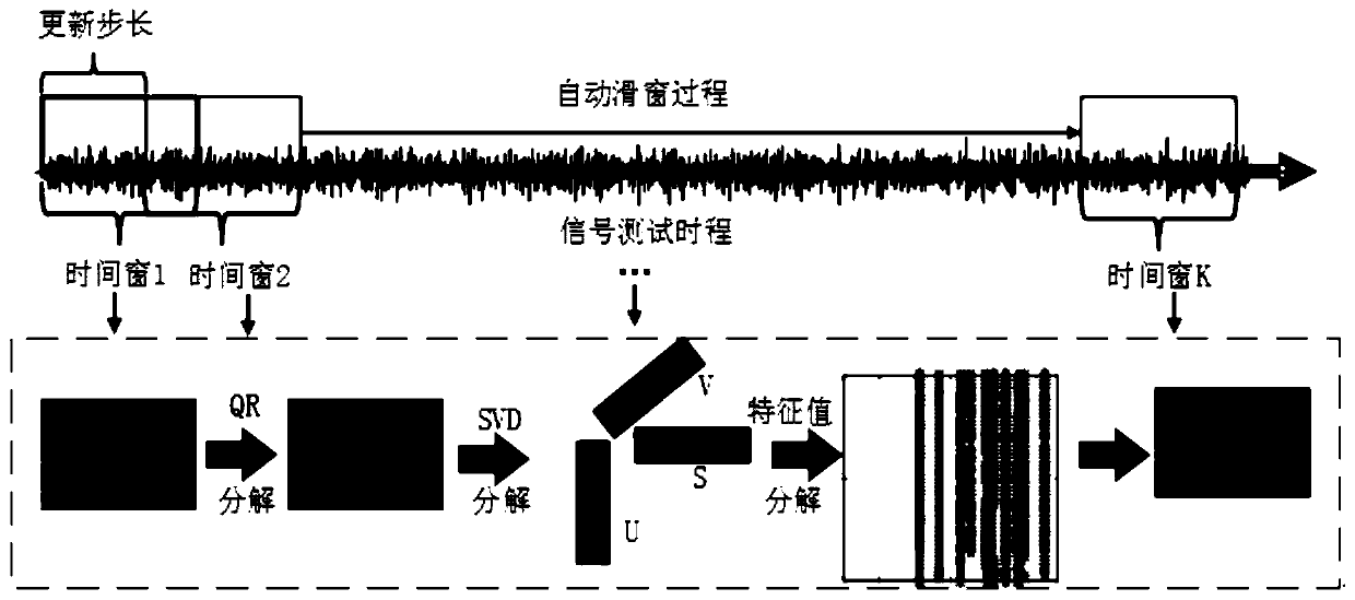
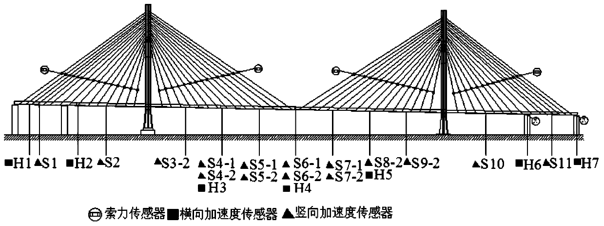
[0191] A curve cable-stayed model bridge with a curvature radius of 27.5m is selected for the impact load test under the intact state, and cable force sensors, lateral acceleration sensors, vertical acceleration sensors and longitudinal acceleration sensors are arranged on the curved cable-stayed model bridge, such as Figure 3-Figure 5 shown. The signal sampling frequency is 256Hz. The initial modal information of the cable-stayed bridge is obtained based on the vibration test signal of the first 8s, and the new modal information of the cable-stayed bridge is obtained every subsequent interval of 0.4s. Respectively adopt the tense quantum space system identification method established by the present invention and the traditional sliding window random subspace system identification method to identify the curved cable-stayed model bridge, so as to compare the continuous identification method of the tense quantum space in the present invention with the traditional sliding window ...

Embodiment 2

[0205] The vibration signal of the concrete bridge tower under the excitation of white noise is selected for the cable-stayed bridge shaking table test, the signal sampling frequency is 256Hz, and the signal acquisition time is 47s. The initial modal information of the cable-stayed bridge pylon is obtained based on the vibration test signal in the first 6s, and the new modal information of the cable-stayed bridge pylon is obtained every subsequent 5s. The TSI method established in this paper and the short-term sliding window determination subspace system identification method (hereinafter referred to as the CSI sliding window method, CSI is Combined Subspace Identification) are used to identify the cable-stayed bridge towers in order to compare the TSI method with the CSI method. performance of the method.

[0206] The stability maps generated by the CSI sliding window method and the TSI method are as follows: Figure 16 and Figure 17 As shown, it can be seen that the syste...


PUM


Abstract

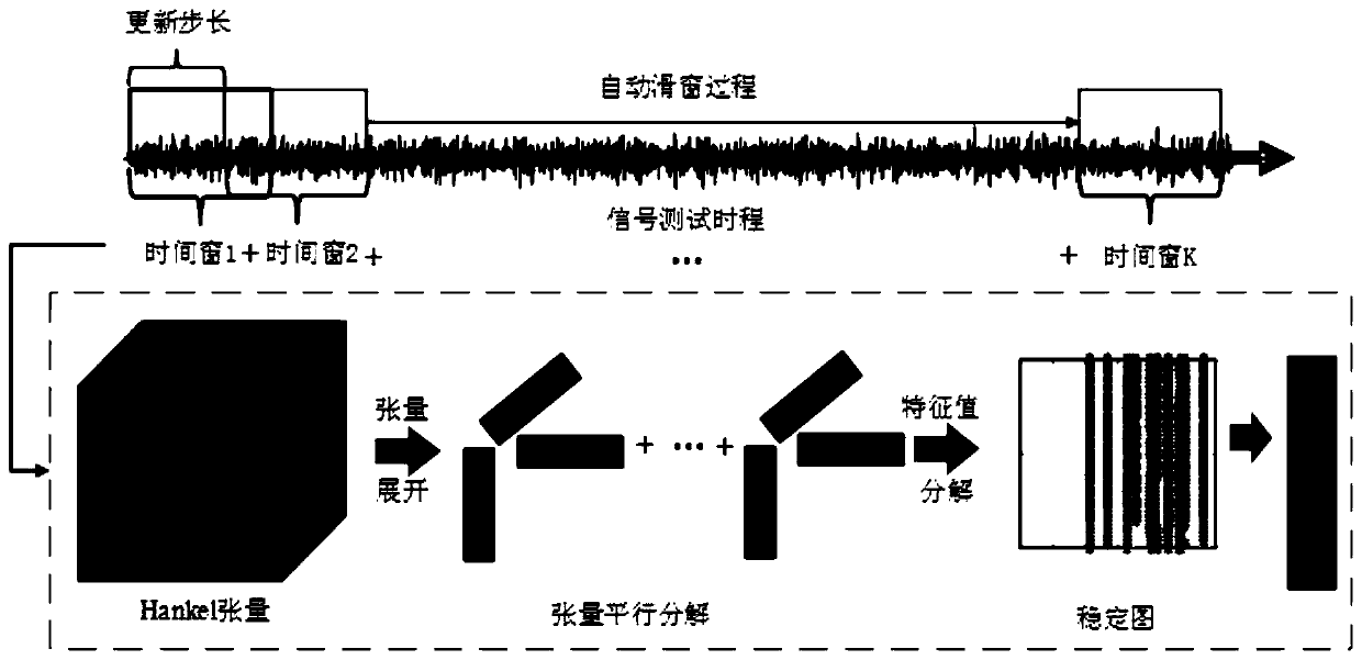
The invention discloses a tensor subspace continuous system identification method of a bridge time-varying system. The method comprises the following steps: acquiring a bridge time-varying signal; dividing the time-varying signal with the signal time history of T into N time windows according to an increasing step length L to obtain Hankel matrixes of the N time windows; establishing a mathematical model for solving a tensor subspace system matrix, wherein Xk=UkSkV<T>+Wk; and solving the tensor subspace system matrix to obtain the frequency fi, k and damping ratio zeta i, k of the ith-order vibration mode of the kth time window and the vibration mode vectors phi k of all orders. According to the invention, the time dimension is introduced; expanding the two-dimensional matrix to a three-dimensional tensor; a time-varying Hankel tensor is established, based on tensor expansion and tensor rapid parallel decomposition theories, system matrix rapid estimation based on tensor operation is realized, calculation efficiency and identification result precision can be improved, modal parameter information of a system can be identified more easily, and a core technical support is provided forreal-time health monitoring of a bridge.

Description

technical field [0001] The invention relates to the field of bridge engineering time-varying nonlinear system identification, in particular to a method for identifying a tensor quantum space continuous system of a bridge time-varying system. Background technique [0002] Traditional bridge inspections generally require bridge inspection engineers to manually inspect the bridge structure. This method is too time-consuming and often requires interruption of traffic. The inspection and evaluation results often vary from person to person, and it is generally difficult to find damage to hidden parts of the structure through manual inspection. , it is difficult to meet the needs of the rapid development of modern transportation. And the structural damage diagnosis technology developed in modern times, that is, intelligent health monitoring technology, is a simple and economical method to assess the safety status of structures. [0003] In recent years, with the vigorous developme...

Claims


Application Information

Patent Timeline
Patent Type & Authority Applications(China)
IPC IPC(8): G06F17/50G06F17/16
CPCG06F17/16
Inventor 张二华单德山
Owner SICHUAN DEPT OF TRANSPORTATION HIGHWAY PLANNING PROSPECTING & DESIGN RES INST
Learn More