Encoder-based locomotive positioning device

A positioning device and encoder technology, which is applied to locomotives, railway signals and safety, etc., can solve problems such as hidden dangers in production safety, difficult installation locations, and errors in locomotive positioning accuracy, so as to ensure smooth progress and avoid potential safety hazards.

Pending Publication Date: 2019-11-05
安徽马钢张庄矿业有限责任公司
View PDF0 Cites 0 Cited by
  • Summary
  • Abstract
  • Description
  • Claims
  • Application Information

AI Technical Summary

Problems solved by technology

However, the above three methods all have disadvantages: if no distance sensor is used, when the electric locomotive starts, accelerates or decelerates, the wheels are prone to slipping, and there is a large error between the actual walking distance of the electric locomotive and the output speed of the motor , leading to positioning errors; if a non-contact Hall sensor is used, there will be a phenomenon of "missing teeth" in the detection, resulting in poor positioning accuracy of the electric locomotive; if a contact encoder with a drive wheel is used, it will bring equipment failure rate High, difficult installation location, complex maintenance, poor positioning accuracy and other defects, the above conditions cause errors in the accuracy of locomotive positioning, bring hidden dangers to safe production, and hinder the smooth progress of underground transportation

Method used


Image

  • Encoder-based locomotive positioning device
  • Encoder-based locomotive positioning device
  • Encoder-based locomotive positioning device

Examples


Embodiment Construction

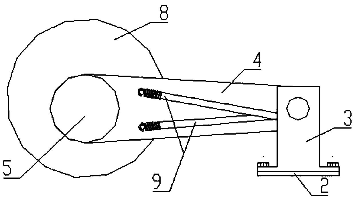
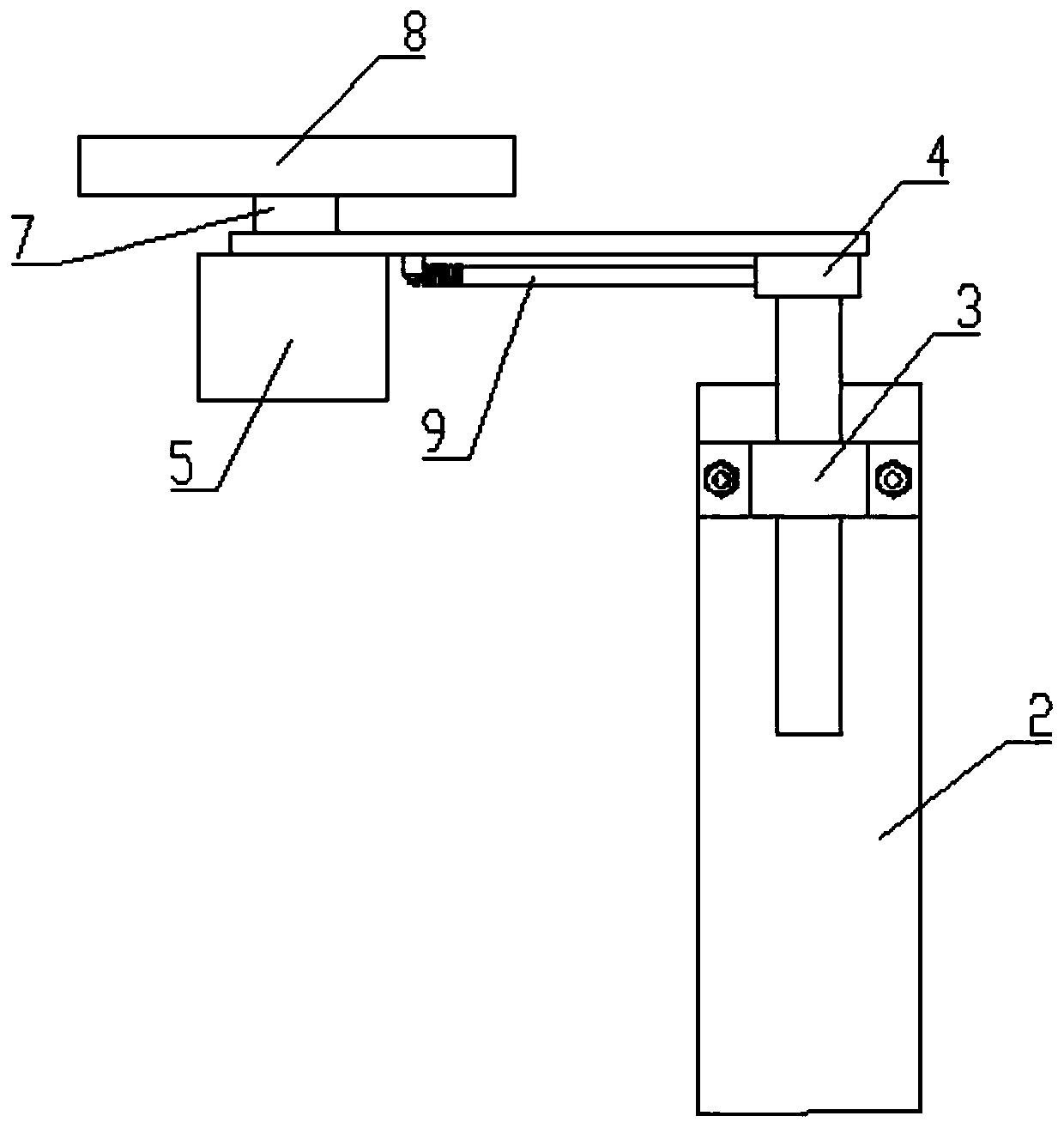
[0017] In the following, the present invention will be further described in detail with reference to the accompanying drawings to facilitate a clearer understanding by those skilled in the art, such as figure 1 , figure 2 , image 3 , Figure 4 As shown, the present invention adopts the following solutions, including:

[0018] The horizontal bracket 2 is installed on the locomotive wheel axle sheath 1. One end of the horizontal bracket is connected to the vertical bracket 3; the swing arm 4 connected to the upper end of the vertical bracket is rotated, and one side of the end of the swing arm is connected to the encoder 5, which is electrically connected The communication cable 6 transmits the data of the encoder to the locomotive controller. The end of the swing arm is rotatably connected to the driven axle 7. One end of the driven axle is matched with the encoder, and the other end of the driven axle is fixed The driven wheel 8 is connected; the end of the swing arm is connect...


PUM


Abstract

The invention discloses an encoder-based locomotive positioning device. The device comprises a horizontal bracket and a swinging arm, wherein the horizontal bracket is mounted on a locomotive wheel axle sheath and one end of the horizontal bracket is connected with a vertical bracket; the swinging arm is rotatably connected with the vertical bracket and one side surface of the end of the swingingarm is connected with an encoder; the encoder is electrically connected with a communication cable; the communication cable is used for transmitting the data of the encoder to a locomotive controller;the end of the swinging arm is rotatably connected with a driven wheel axle; one end of the driven wheel axle is matched with the encoder and the other end of the driven wheel axle is fixedly connected with a driven wheel; the end of the swinging arm is connected with a spring; and the other end of the spring is connected with the vertical bracket to ensure that the peripheral surface of the driven wheel is in tight contact with the outer peripheral surface of a locomotive wheel. According to the device, a control center is capable of correctly grasping the positions of the locomotives in real time and accurately operating the loading/unloading and operation of the locomotives, so as to avoid the potential safety hazards and ensuring the smooth proceeding of the underground transportation.

Description

Technical field [0001] The invention belongs to the field of mine transportation, and particularly relates to an encoder-based locomotive positioning device. Background technique [0002] At present, most of the underground transportation in mines uses unmanned electric locomotives. In order to understand the operating position of the electric locomotive in real time and accurately, there must be a device for precise positioning of the electric locomotive. At present, the method of positioning the electric locomotive There are many kinds of them, among which three are the more common ones: 1. Without using any distance sensor, the running distance of the electric locomotive can be calculated by the frequency output by the inverter, the speed of the motor and the gear ratio of the gearbox; 2. Non-contact The hall sensor of the form obtains the running distance of the electric locomotive by counting the number of back-end gears of the motor code disk; third, the contact type encode...

Claims


Application Information

Patent Timeline
Patent Type & Authority Applications(China)
IPC IPC(8): B61C17/00B61L25/02
CPCB61C17/00B61L25/02
Inventor 张慧东吴新义李东刘明明余剑靳群王邦策郭春华王玉富刘建东
Owner 安徽马钢张庄矿业有限责任公司
Why Eureka
Try Eureka