Multidirectional transmission mechanism for materials in batches, and method for processing spiced beef based on the mechanism
A transmission mechanism and material technology, applied in the direction of conveyors, metal processing, mechanical conveyors, etc., can solve the problems of inconvenient changes, unfavorable rear road concentration, and insufficient flexibility of different-direction transportation, so as to save the cost of man-made concentration in the middle link effect
- Summary
- Abstract
- Description
- Claims
- Application Information
AI Technical Summary
Problems solved by technology
Method used
Image
Examples
Embodiment 1
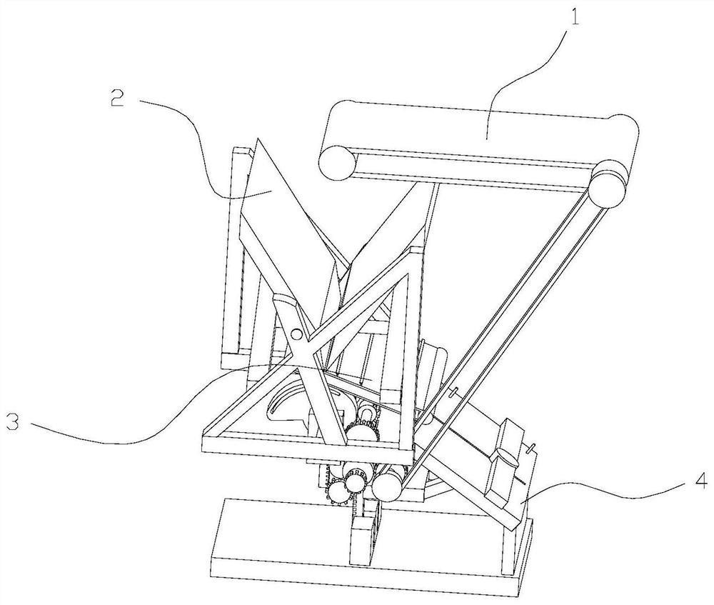
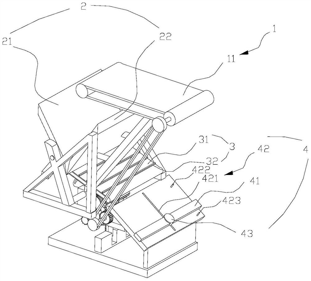
[0067] like figure 1 , 2 As shown in the figure, this embodiment discloses a material batch multidirectional transmission mechanism. Specifically, the present invention is disclosed by taking the delivery of thawed beef nuggets as an example. Of course, the material batch multidirectional transmission mechanism of the present invention is not limited to To transport the thawed beef nuggets, other materials adopt the batch multidirectional transmission mechanism of the present invention to realize the batch multidirectional transport function, which should also fall within the protection scope of the present invention.
[0068] The material batch multi-directional transmission mechanism includes an intermittent material conveying device 1, a material batch unloading device 2, an inclined transfer device 3, and a movable guide device 4 in sequence from front to back in the process flow.
[0069] The material batch feeding device 2 includes a first baffle plate 21, a second baff...
Embodiment 2
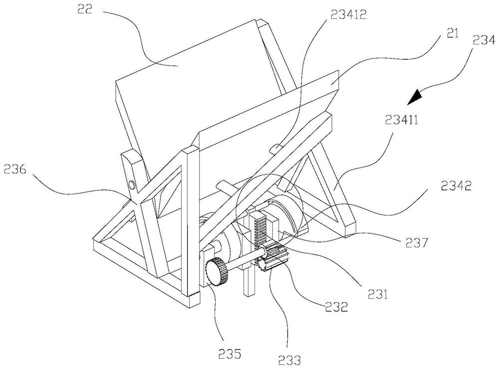
[0078] like image 3 , 4 As shown, this embodiment discloses a specific first drive device, including a first gear rod 231, a first incomplete gear 232, a first complete gear 233, a first rotating bracket 234, a first rotating seat 235, a second The rotating bracket 236 and the second rotating base 237 . The first incomplete gear 232 can alternately engage with the first gear rod 231 and the first complete gear 233 , and the first complete gear 233 is meshed with the first gear rod 231 . The first rotating bracket 234 is rotatably engaged with the first rotating seat 235, the second rotating bracket 236 is rotatably engaged with the second rotating seat 237, the first rotating bracket 234 is connected with the first blocking plate 21, and the second rotating bracket 236 is connected with the first rotating bracket 236. The two baffle plates 22 are connected. A first guide groove 2341 and a second guide groove (not shown in the figure) are respectively opened on the first ro...
Embodiment 3
[0083] like image 3 , 4 As shown, the difference between this embodiment and the above-mentioned embodiment is that the structures of the first rotating bracket 234 and the second rotating bracket 236 are the same. Reference is made to the first rotating bracket 234 . The first rotating support 234 includes a support body, a rotating shaft (not shown in the figure), and a rotating member 2342. The rotating member 2342 and the support body are all sleeved in the rotating shaft, and the rotating shaft is rotatably connected to the corresponding rotating seat. . The rotating member 2342 is provided with a corresponding guide groove, namely the first guide groove 2341 here. The guide groove starts from the end closest to the rotation center point of the rotating member 2342, and bends and extends to form the other end as the distance gradually increases. One end of the first guide groove 2341 on the first rotating bracket 234 is misaligned with one end of the second guide groo...
PUM
 Abstract
Description
Claims
Application Information
 - R&D Engineer
- R&D Manager
- IP Professional
- Industry Leading Data Capabilities
- Powerful AI technology
- Patent DNA Extraction
Browse by: Latest US Patents, China's latest patents, Technical Efficacy Thesaurus, Application Domain, Technology Topic, Popular Technical Reports.
© 2024 PatSnap. All rights reserved.Legal|Privacy policy|Modern Slavery Act Transparency Statement|Sitemap|About US| Contact US: help@patsnap.com


