Underground pipe network information management system
An information management system and underground pipe network technology, applied in the field of underground pipe network information management system, can solve the problems of inconvenient cable quantity and too many cable pipes, etc., and achieve the effect of fast information transmission
- Summary
- Abstract
- Description
- Claims
- Application Information
AI Technical Summary
Problems solved by technology
Method used
Image
Examples
Embodiment 1
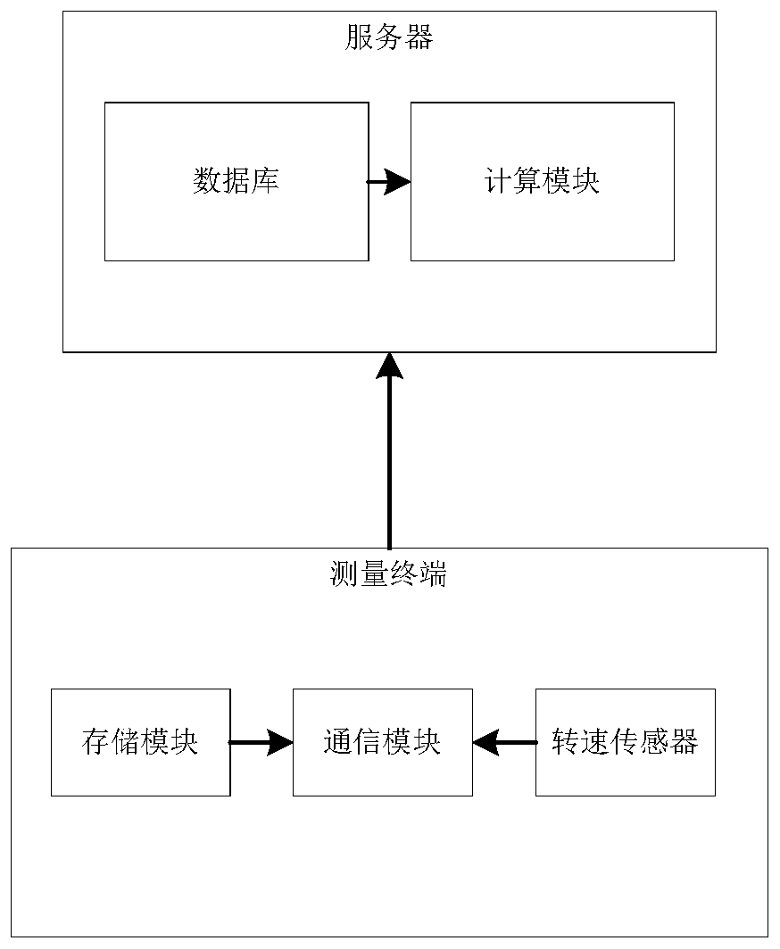
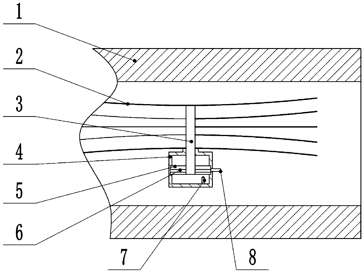
[0033] Embodiment one is basically as attached figure 1 Shown: The underground pipe network information management system includes a server, measurement components and measurement terminals. The server includes a database and a calculation module. The measurement terminal includes a storage module, a communication module and a speed sensor 7. The storage module uses a memory, and the memory model is MX25L6445E. The communication module adopts a 4G communication module or a 5G communication module, and a 5G communication module is preferred in this embodiment. And the communication module is electrically connected with the rotational speed sensor 7, and the model of the rotational speed sensor 7 is an eddy current rotational speed sensor 7 of KD2446, such as figure 2 As shown, the measurement assembly includes a housing box 4 and a binding piece 3 for binding the cables 2, and the binding piece 3 is a corrosion-resistant polytetrafluoroethylene sampling plastic rope.
[0034]...
Embodiment 2
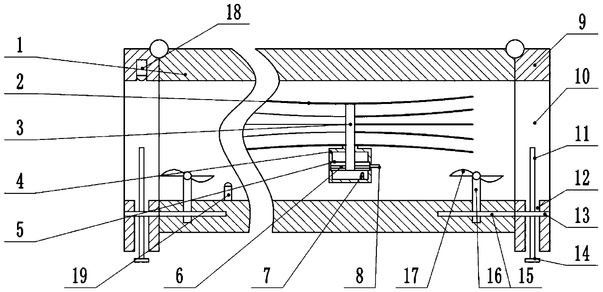
[0042] The difference between embodiment two and embodiment one is that, as image 3 and Figure 4 As shown, it also includes a pipe cover 9 and a liquid level sensor 19. There are two pipe covers 9 and they are respectively located at the left and right pipe openings, and the pipe cover 9 is hinged with the pipe wall. The pipe cover 9 is opened from left to right. A through groove 10, the vertical distance of the first through groove 10 is the same as the pipe mouth diameter, the first through groove 10 communicates with the pipe mouth, and the lower side wall of the first through groove 10 of the pipe cover 9 has a through hole from top to bottom 12. One end of the through hole 12 communicates with the outside world, and the other end communicates with the first through groove 10, and the left and right side walls of the through hole 12 are provided with a first placement through groove 6, and a driven gear 13 is placed in the first placement through groove 6, The driven ge...
specific Embodiment approach
[0045] When it rains outside or when there is water flow in the pipeline 1, the liquid level sensor 19 detects that the liquid level rises, and sends the liquid level information to the communication module, and the communication module transmits the liquid level information to the server, and the database in the server sends the liquid level information The information is stored. It is convenient for inspectors to understand the liquid level in the pipeline 1 at this time, and if the water flow in the pipeline 1 flows from left to right, the water flow in the pipeline 1 will drive the fan blade 17 to rotate, and the rotation of the fan blade 17 will drive the rotation shaft 16 to rotate in turn , the driving gear 15 and the driven gear 13 rotate, because the telescopic rod 11 is coaxial and threaded with the driven gear 13, and the left and right two telescopic rods 11 rotate in opposite directions, so under the flow of water from left to right, the left and right The driven ...
PUM
 Abstract
Description
Claims
Application Information
 - R&D
- Intellectual Property
- Life Sciences
- Materials
- Tech Scout
- Unparalleled Data Quality
- Higher Quality Content
- 60% Fewer Hallucinations
Browse by: Latest US Patents, China's latest patents, Technical Efficacy Thesaurus, Application Domain, Technology Topic, Popular Technical Reports.
© 2025 PatSnap. All rights reserved.Legal|Privacy policy|Modern Slavery Act Transparency Statement|Sitemap|About US| Contact US: help@patsnap.com


