A kind of expansion valve and air supply enthalpy increasing system
An expansion valve and valve body technology, applied in the field of expansion valves, can solve the problems of many connection points, complex pipelines, adverse effects on system reliability, etc.
- Summary
- Abstract
- Description
- Claims
- Application Information
AI Technical Summary
Problems solved by technology
Method used
Image
Examples
Embodiment 1
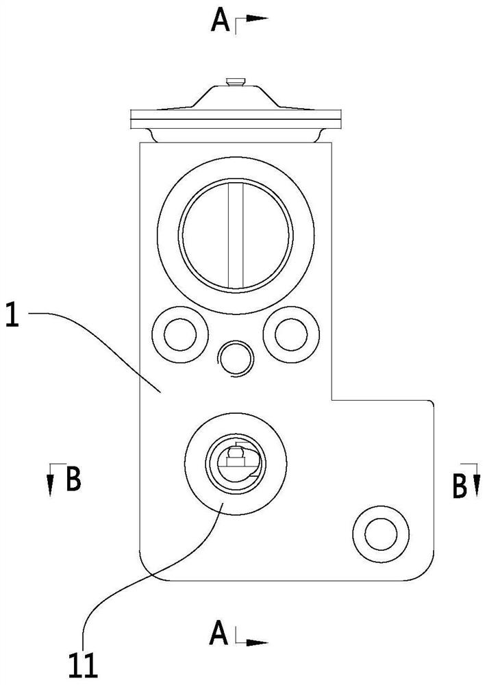
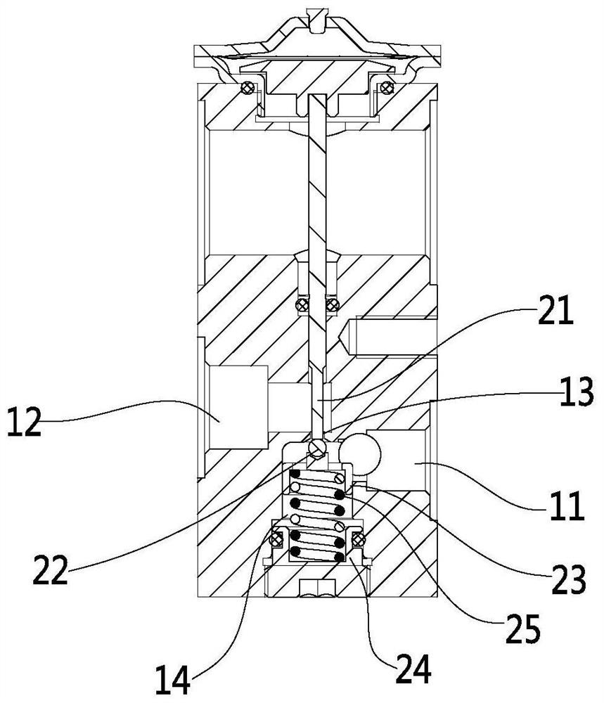
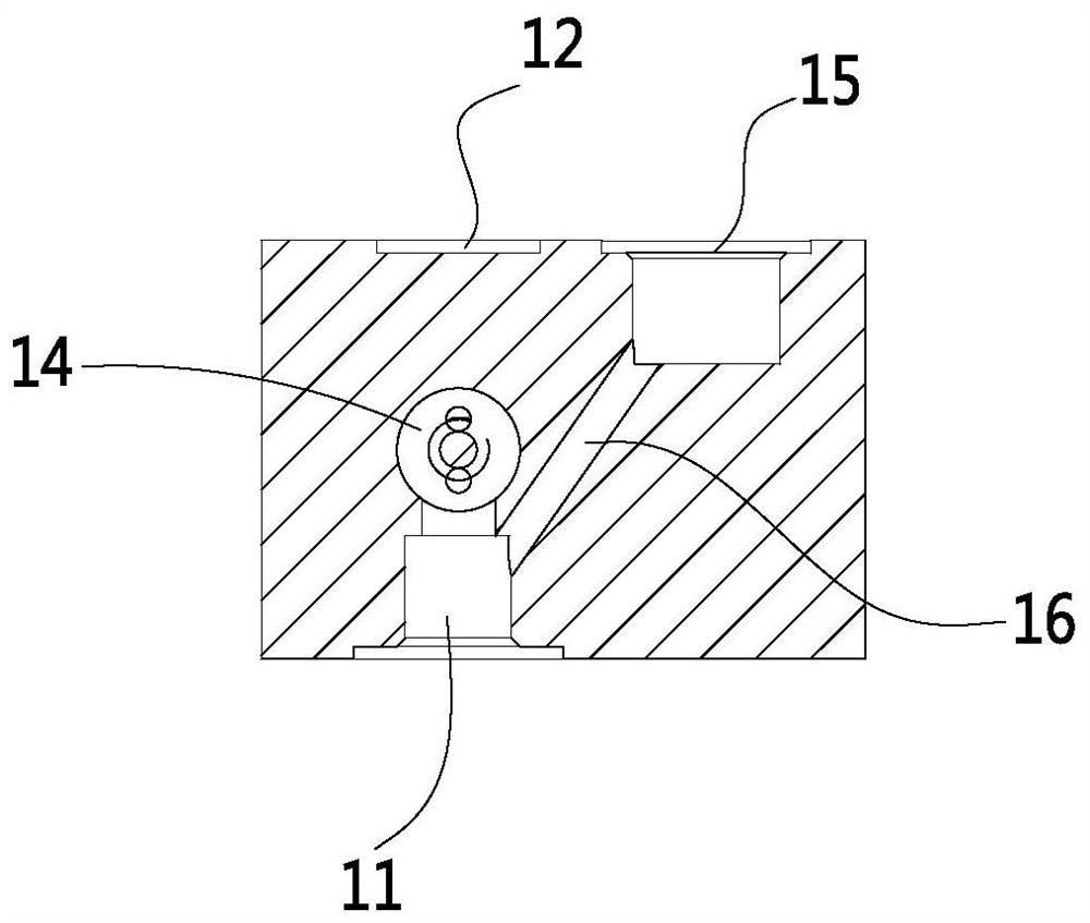
[0036] like Figure 1 to Figure 3 As shown, the expansion valve in this embodiment is a thermal expansion valve, including a valve body 1 and a valve core assembly. The valve body 1 is provided with an inlet 11, a first outlet 12, a throttling hole 13 and a throttling cavity 14, throttling The chamber 14 communicates with the inlet 11 , the first outlet 12 and the inlet 11 are arranged on two opposite sides of the valve body 1 , and the throttling chamber 14 communicates with the first outlet 12 through the throttling hole 13 . The spool assembly includes a driver, a valve stem 21, a spool 22 and a reset assembly. The reset assembly includes a spool seat 23 arranged in the throttle chamber 14, a mounting seat 24 and a return spring 25. The return spring 25 is clamped on the spool. Between the seat 23 and the mounting seat 24, the driving part drives the valve rod 21 to push the valve core 22 to move downward and compress the return spring 25 to open the orifice 13. At this tim...
Embodiment 2
[0042] like Figures 4 to 6 As shown, the thermal expansion valve in this embodiment also includes a solenoid valve 4 installed on the valve body 1. The valve body 1 is provided with a valve chamber 18 communicating with the orifice 13. connected to the valve port 181, the solenoid valve includes a solenoid valve core 41 installed in the valve cavity 18, an electromagnetic driver and a return spring. There is no communication between the orifice 13 and the first outlet 12 . After the return spring drives the electromagnetic valve core 41 to reversely move and reset, the valve port 181 is opened, and the inlet 11 is connected to the first outlet 12 at this time. By designing the solenoid valve, it can be ensured that when the spool 22 cannot close the orifice 13 under normal working conditions, the solenoid spool can close the valve port 181 to close the connection between the first outlet 12 and the inlet 11 to realize the cut-off function.
Embodiment 3
[0044] like Figures 7 to 10 As shown, the expansion valve in this embodiment is an electronic expansion valve, including a valve body 1 and a valve core assembly. The valve body 1 is provided with an inlet 11, a first outlet 12 and an orifice 13. The valve body 1 includes a split molding The body and the valve sleeve, the inlet 11 and the first outlet 12 are arranged on the body, the body is provided with a valve cavity, the valve sleeve is installed in the valve cavity, the throttle hole 13 is an axial through hole located at the bottom of the valve sleeve, the valve The sleeve is provided with a radial through hole for communicating with the first outlet 12 and the orifice 13, and the bottom opening of the orifice 13 is in communication with the inlet 11. The valve core assembly includes an electromagnetic driver 51 and a valve needle 52, and the valve needle 52 slides Installed in the valve sleeve, and driven by the electromagnetic driver 51 to reciprocate along the axial ...
PUM
 Abstract
Description
Claims
Application Information
 - R&D Engineer
- R&D Manager
- IP Professional
- Industry Leading Data Capabilities
- Powerful AI technology
- Patent DNA Extraction
Browse by: Latest US Patents, China's latest patents, Technical Efficacy Thesaurus, Application Domain, Technology Topic, Popular Technical Reports.
© 2024 PatSnap. All rights reserved.Legal|Privacy policy|Modern Slavery Act Transparency Statement|Sitemap|About US| Contact US: help@patsnap.com


