
Water discharge structure with anti-floating, seepage-proofing and filtering functions

A drainage structure and function technology, applied in the field of construction, can solve problems such as sand particles easily clogging rock layers, frequent changes in groundwater levels, and reducing the bearing capacity of foundation soil, so as to solve the problem of reverse seepage, save water and energy, and improve bearing capacity. The effect of pressure

Pending Publication Date: 2019-11-01
黄逸飞 +1
View PDF0 Cites 0 Cited by
  • Summary
  • Abstract
  • Description
  • Claims
  • Application Information

AI Technical Summary

Problems solved by technology

[0004] Driving anti-floating anchor rods and anti-floating piles underground can achieve the purpose of anti-floating to a certain extent, but this kind of construction period is long and the cost is high. The cost of driving an anti-floating pile is about tens of thousands to more than ten Moreover, it is difficult to reasonably determine the water level of anti-floating installations. If there are cracks on the ground, it will also cause underground water seepage and reverse seepage. Moreover, severe torrential rains will continue to occur with global climate warming, resulting in frequent changes in groundwater levels. The existing anti-floating There are certain risks in the structure, and it is difficult to meet the anti-floating requirements of building structures;
[0005] Dig trenches on the ground, and introduce groundwater into catchment wells and culverts through trenches. However, this method has the following defects: (1) It is only suitable for areas with small groundwater volume and small drainage area. When the groundwater volume is large, it is completely It cannot meet the demand; (2) When the groundwater in the foundation soil reverses infiltration, it directly enters the ditch with sand particles, causing blockage of the ditch and the water collection well, so the staff needs to go to the water collection well to clean up the sludge; some water from the water collection well passes through The water pump is used to extract and discharge water, but when the water mixed with sand particles passes through the blades of the water pump, it is easy to hinder or even damage the blades, and the maintenance and replacement costs are high; (3) In the actual excavation process, the foundation soil needs to be excavated into trenches, The soil in the ditch is transferred to other places, and then the water in the ditch is drained with a pump, then filled with large stones and covered with geotextiles, and finally the original soil in the ditch is transported back to be covered with geotextiles. It not only destroys the bearing layer of the foundation soil, but also greatly disturbs the foundation soil, reducing the bearing capacity of the foundation soil. It also has high costs and a long construction period. The excavated foundation soil needs to be transported back and forth. The effect is poor; (4) During the flood season, the ground absorbs a large amount of rainwater, and after the flood season, the groundwater reverses and generates upward water pressure. Green areas and underground parking areas in residential areas;

Method used


Image

  • Water discharge structure with anti-floating, seepage-proofing and filtering functions
  • Water discharge structure with anti-floating, seepage-proofing and filtering functions
  • Water discharge structure with anti-floating, seepage-proofing and filtering functions

Examples


Embodiment approach

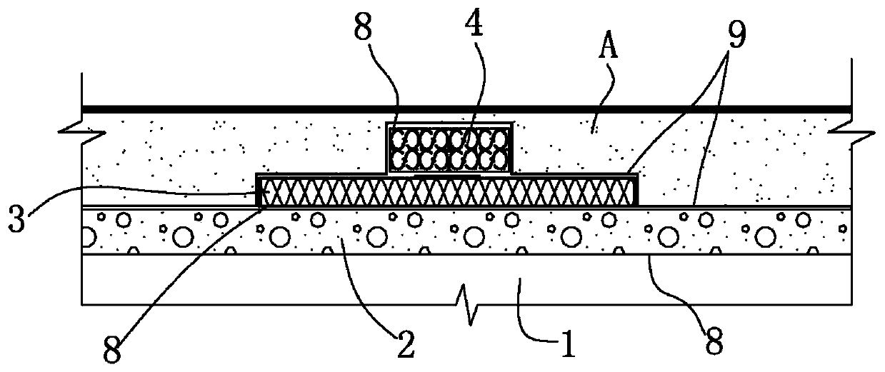
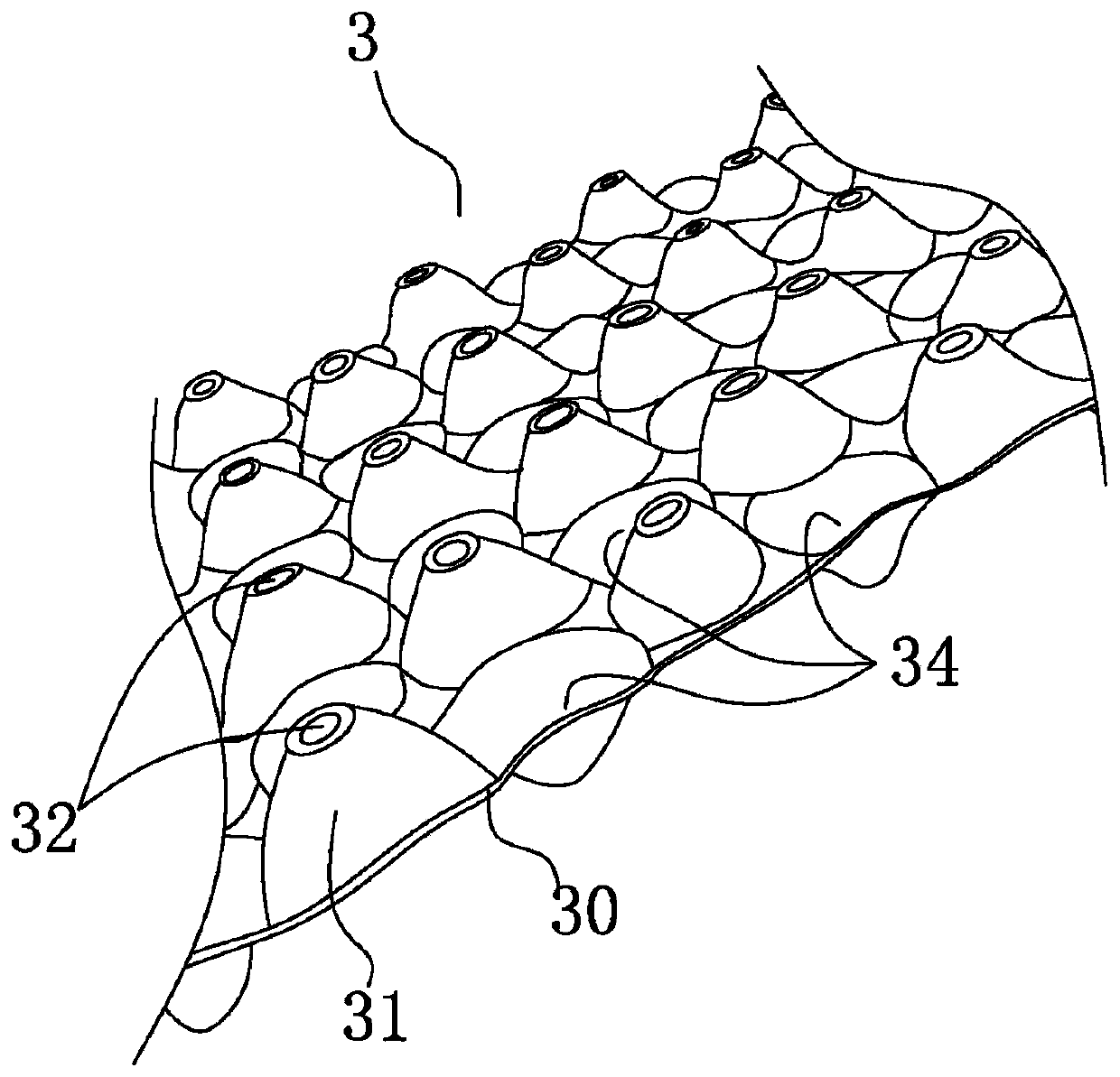
[0040] Specific implementation methods, such as Figure 1-6 As shown, a drainage structure with anti-floating, anti-seepage and filtering functions according to the present invention mainly includes the following parts: a water-passing layer 2 (gravel or sandstone layer), a water-filtering layer 3, and some water guide plates 40 , PVC casing joint (not shown in the figure), geotextile 8 and plastic film layer 9;

[0041] During actual construction, the construction sequence includes finishing the foundation soil 1 side, fully paving the first anti-silting geotextile 8, laying the water-permeable layer 2 (gravel or sand layer), construction of the water filtration layer 3, construction of the drainage layer 4, Lay plastic film layer 9 construction and drainage layer 4 sets to connect to catchment culverts, catchment wells, etc.;

[0042] 1. Finishing of the foundation soil surface: the anti-silting geotextile 8 is covered on the foundation soil surface; the first surface of th...


PUM

PropertyMeasurementUnit
Outer diameteraaaaaaaaaa

Abstract

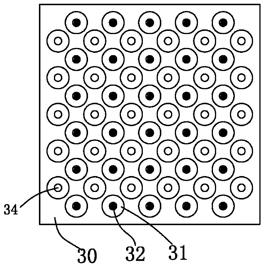
The invention discloses a water discharge structure with anti-floating, seepage-proofing and filtering functions. The water discharge structure is laid on foundation soil, is used for discharging andguiding reverse seepage water flowing from the underground to the ground and comprises a water passing layer, a water filtering layer and a water discharging layer which are arranged from bottom to top in sequence, wherein the water passing layer is laid on the foundation soil and is used for dredging underground seepage water; the water filtering layer is used for depositing the underground seepage water of the water passing layer and guiding the underground seepage water to the water discharging layer and comprises a plurality of protrusion portions and a base layer, all the protrusion portions are alternately arranged on the base layer in a matrix form and are further provided with water passing passages correspondingly, and the positions, on the base layer, between all the protrusion portions form sunken portions used for depositing and filtering the underground seepage water correspondingly; and the water discharging layer is laid facing the water filtering layer and is used for guiding and discharging out the underground seepage water of the water filtering layer. By means of the water discharge structure with the anti-floating, seepage-proofing and filtering functions, the water discharge structure with the anti-floating, seepage-proofing and filtering functions is provided, the water discharge structure is simple in structure, reasonable in design and easy to realize, rapid water discharging is achieved, and meanwhile, the water discharge structure further has the effect of filtering the underground water.

Description

technical field [0001] The invention relates to the construction industry, in particular to a drainage structure with the functions of anti-floating, anti-seepage and filtering. Background technique [0002] As we all know, preventing groundwater reverse seepage is an important link in urban construction, especially in some super high-rise basements, underground commercial streets, underground passages, subway stations, etc. Ground buildings pose a great threat, so it is necessary to take measures to prevent groundwater infiltration from large-scale urban construction to small residential quarters; [0003] The existing measures to solve the anti-seepage arched ground are as follows: [0004] Driving anti-floating anchor rods and anti-floating piles underground can achieve the purpose of anti-floating to a certain extent, but this kind of construction period is long and the cost is high. The cost of driving an anti-floating pile is about tens of thousands to more than ten ...

Claims


Application Information

Patent Timeline
IPC IPC(8): E02D3/10E02D3/00E02D31/12
CPCE02D3/10E02D3/005E02D31/12
Inventor 黄逸飞
Owner 黄逸飞
Learn More