
Realization method for preventing damage of core of cable wire

A realization method and cable technology, applied in the direction of cable installation, dismantling/armored cable equipment, cable installation device, etc., can solve the problems of cable damage, staff difficulty, danger, etc., and achieve the effect of avoiding damage

Inactive Publication Date: 2019-10-29
李林
View PDF0 Cites 2 Cited by
  • Summary
  • Abstract
  • Description
  • Claims
  • Application Information

AI Technical Summary

Problems solved by technology

[0002] When installing cables, it is often necessary to peel the cables. Since the outer skin of the cables has a protective effect and is relatively strong, it is not an easy task to peel the cables, which is time-consuming and laborious.
The traditional tool for stripping the cable sheath is to use tools such as electrician's knife, hook knife or wallpaper knife. Because the cable sheath is very hard, during construction, construction workers often cut their hands or cut their work clothes or even cut other parts of their bodies. The occurrence of bleeding incidents, especially in winter construction, the cable sheath will be hardened, it will be more difficult to peel it off with ordinary tools, and excessive force will be more dangerous, so it is very important to use such tools in the process of peeling the cable sheath. It is not safe. In the process of peeling the cable with tools, the tool is easy to damage the cable core, causing damage to the cable. At the same time, in the winter environment, a layer of ice will condense on the outer skin of the cable, which will cause serious damage to the staff. caused certain difficulties

Method used


Image

  • Realization method for preventing damage of core of cable wire
  • Realization method for preventing damage of core of cable wire
  • Realization method for preventing damage of core of cable wire

Examples


Embodiment

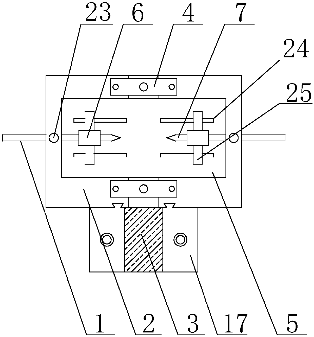
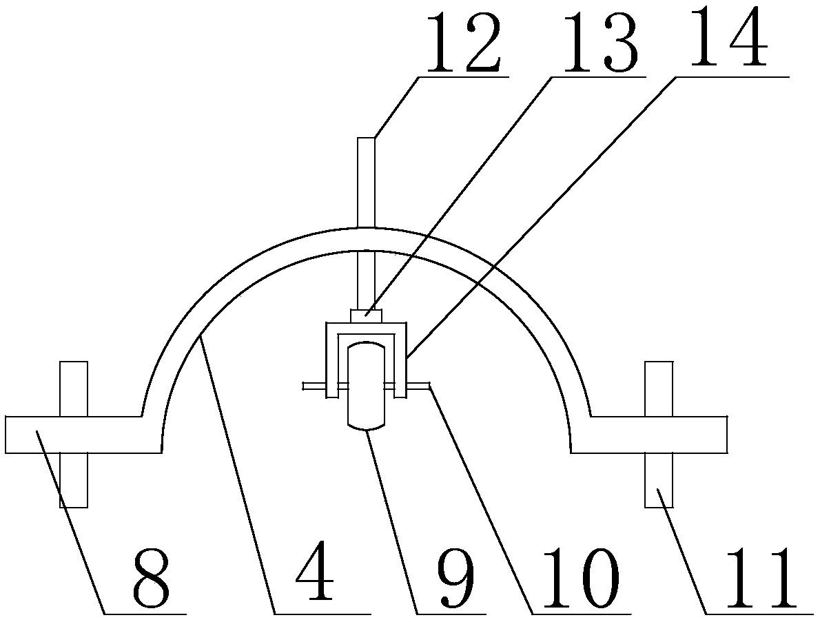
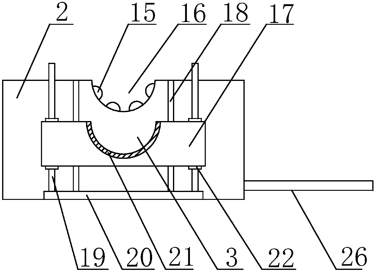
[0027] Such as Figure 1 to Figure 3 As shown, the implementation method of the present invention to prevent damage to the cable wire core includes the following steps: first place the cable to be stripped in the second arc-shaped groove 16 of the support seat 2, rotate the fixing rod 12, and force the roller 9 to The cable is pressed in the second arc-shaped groove 16, and then the movable rod 1 is pushed to force the cutter head 7 to be inserted into the outer skin of the cable, and the adjusting rod 23 is rotated so that the adjusting rod 23 fixes the movable rod 1 on the support base 2 on, and then rotate the stop rod 24 to force the two sides of the cable to be limited by the stop rod 24 to prevent the cable from moving to both sides, and then loosen the fastening ring 22 on the support rod 19 to adjust the movable table 17 height, so that the cable is in the first arc-shaped groove 3, the heating wire in the heating layer 21 is energized, and finally when the cable is pu...


PUM


Abstract

The invention discloses a realization method for preventing damage of a core of a cable wire. The method includes the following steps: firstly placing a to-be-stripped cable wire in second arc-shapedgrooves of a supporting seat; rotating a fixation rod, forcing a rolling wheel to press the cable wire in the second arc-shaped grooves; then pushing movable rods to force cutter heads to be insertedinto a sheath of the cable wire; rotating adjustment rods to allow the adjustment rods to make the movable rods fixed on the supporting seat; then rotating limit rods to force both sides of the cablewire to be limited by the limit rods to prevent the cable wire from moving to the both sides; then loosening fastening rings on supporting rods, adjusting the height of a movable platform to make thecable wire located in a first arc-shaped groove, and powering up heating wires in a heating layer; and finally, pulling the cable wire, and stripping the sheath of the cable wire by cutter heads on both sides during a process of movement of the cable wire.

Description

technical field [0001] The invention relates to the technical field of cables, in particular to a realization method for preventing damage to cable cores. Background technique [0002] When installing cables, it is often necessary to peel the cables. Since the outer skin of the cables has a protective effect and is relatively strong, it is not an easy task to peel the cables, and it is time-consuming and laborious. The traditional tool for stripping the cable sheath is to use tools such as electrician's knife, hook knife or wallpaper knife. Because the cable sheath is very hard, during construction, construction workers often cut their hands or cut their work clothes or even cut other parts of their bodies. The occurrence of bleeding incidents, especially in winter construction, the cable sheath will be hardened, it will be more difficult to peel it off with ordinary tools, and excessive force will be more dangerous, so it is very important to use such tools in the process o...

Claims


Application Information

Patent Timeline
IPC IPC(8): H02G1/12
CPCH02G1/126H02G1/127H02G1/1275
Inventor 李林
Owner 李林
Learn More