
LED projection lamp

A technology of LED floodlights and LED light sources, which is applied in the field of lamps and lanterns, can solve the problems of uneven illumination, small adjustment range of light-emitting angle, and unfriendly structural design, and achieve the adjustment of installation angle and light-emitting angle, flexible installation angle and light-emitting Angle, heat dissipation structure is stable and reliable

Inactive Publication Date: 2019-10-29
曾宋华
View PDF0 Cites 0 Cited by
  • Summary
  • Abstract
  • Description
  • Claims
  • Application Information

AI Technical Summary

Problems solved by technology

Existing LED floodlights are generally independently illuminated, with a narrow lighting range and limited lighting brightness. If you encounter a large-area lighting place, you need to expand the lighting range or enhance the lighting brightness, and you can only use multiple LED floodlights. Working together to meet the brightness requirements, such an operation is inconvenient and unsightly, and multiple LED floodlights are placed together to make the illumination uneven due to the placement angle or position, and the power lines are pulled separately, which is very troublesome to install and use ; or to replace other LED floodlights with high power or large lighting area, you need to purchase LED floodlights again, which is very impractical and uneconomical, and installation and replacement are troublesome and inconvenient to operate; if in the production process, by changing the production Molds are used to remanufacture LED floodlights with strong lighting brightness or large irradiation area to meet customer needs. This requires re-opening the mold, increasing production and development costs, and increasing manufacturing costs, which is not conducive to the marketing of LED floodlights.
In addition, in order to improve the heat dissipation efficiency, the back of the lamp housing of the existing LED floodlight will extend a number of fixed heat dissipation fins outwards. Such heat dissipation fins are of a fixed structure. The arrangement cannot be changed, the structure is traditional and old, and the structure design is not humanized enough
In addition, the existing heat dissipation fins generally do not have the function of ventilation and heat dissipation, and the heat dissipation efficiency is difficult to ensure
In addition, the existing LED floodlights have a small adjustment range for installation angle and light emission angle, and the irradiation surface and light emitting surface are narrow.

Method used


Image

  • LED projection lamp
  • LED projection lamp
  • LED projection lamp

Examples


Embodiment Construction

[0017] It should be understood that the specific embodiments described here are only used to explain the present invention, not to limit the present invention.

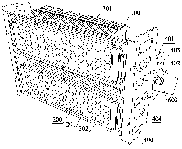
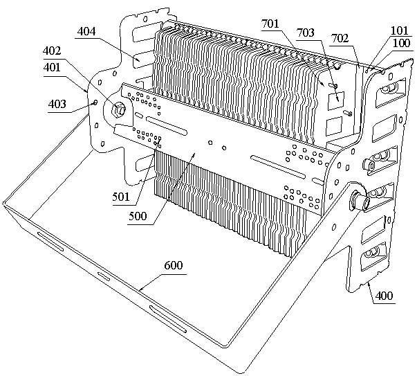
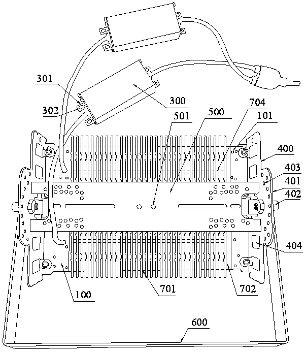
[0018] refer to Figure 1 to Figure 3 , an embodiment of an LED floodlight according to the present invention is proposed, which includes a plurality of light source mounting plates 100 that can be arranged and spliced, an LED light source structure disposed on the front end of the light source mounting plate 100, and a light-transmitting light cover disposed on the LED light source structure. The board 200, the driving device 300 electrically connected to the LED light source structure, the side frame 400 that is fixed on both sides of the light source mounting plate 100 and assembles all the light source mounting plates 100, and the connection between the two side frames 400 The connecting frame 500 for fixing, and the installation and adjustment frame 600 installed on the side frame 400 for installation and angle a...


PUM


Abstract

The invention discloses an LED projection lamp. The LED projection lamp comprises a plurality of light source mounting plates which can be arranged and spliced, an LED light source structure, light transmitting plates, driving devices, side frames mounted and fixed to the two sides of the light source mounting plates, a connecting frame mounted between the two side frames, and a mounting adjustingframe mounted on the side frames, wherein the back surface of each light source mounting plate is fixedly provided with a cooling structure formed by arranging and splicing a plurality of cooling fins; a plurality of rivet holes are densely formed in the back surface of each light source mounting plate; the cooling fins are fixed to the back surface of each light source mounting plate through rivets and the rivet holes in a riveted mode; the mounting number, the mounting positions and the arrangement mode of the cooling fins can be determined according to requirements; each cooling fin comprises a cooling fin part and a mounting strip part perpendicular to the bottom of the cooling fin part; the mounting strip parts are fixed on the light source mounting plates through rivets in a rivetedmode; each cooling fin part is provided with a plurality of ventilating and cooling holes with ventilation and convection effects; and each cooling fin part extends towards the side surfaces to forma plurality of limiting and fixing strips with limiting and fixing effects.

Description

technical field [0001] The invention relates to the technical field of lamps, in particular to an LED floodlight. Background technique [0002] With the continuous breakthrough of LED technology, especially the successful development of high-power and high-efficiency LEDs, LEDs are widely used in various lighting fields, such as LED floodlights. Existing LED floodlights are generally independently illuminated, with a narrow lighting range and limited lighting brightness. If you encounter a large-area lighting place, you need to expand the lighting range or enhance the lighting brightness, and you can only use multiple LED floodlights. Working together to meet the brightness requirements, such an operation is inconvenient and unsightly, and multiple LED floodlights are placed together to make the illumination uneven due to the placement angle or position, and the power lines are pulled separately, which is very troublesome to install and use ; or to replace other LED floodli...

Claims


Application Information

Patent Timeline
Patent Type & Authority Applications(China)
IPC IPC(8): F21S8/00F21V14/02F21V19/00F21V5/04F21V31/00
CPCF21S8/00F21V5/04F21V14/02F21V19/00F21V29/763F21V29/89F21V31/005F21Y2115/10
Inventor 曾宋华
Owner 曾宋华
Learn More