
Material unwinding system and material unwinding control method

A control method and material technology, which is applied in the field of tire building, can solve problems such as poor tire quality, waste materials, and affecting the tire building process, and achieve the effect of constant tension

Inactive Publication Date: 2019-10-29
SAFE RUN & HISCENT MACHINERY SUZHOU
View PDF2 Cites 6 Cited by
  • Summary
  • Abstract
  • Description
  • Claims
  • Application Information

AI Technical Summary

Problems solved by technology

[0005] There are at least the following disadvantages in the existing technical solutions: during the material guiding process, since the material roller always needs to have a braking force so as to control the material roller to stop at any time, when the pad cloth pulls the material roller to make it rotate, the material roller The material to be guided on the top will slowly tighten and become tighter and tighter, which will change the tension of the pad cloth, which will cause the material to stick more and more tightly to the pad cloth and make it difficult to guide the material out, not only It will cause a large amount of waste and affect the normal production of the equipment. At the same time, it will also cause material stretching, which will affect the tire building process, and in serious cases will cause poor tire quality.

Method used


Image

  • Material unwinding system and material unwinding control method
  • Material unwinding system and material unwinding control method
  • Material unwinding system and material unwinding control method

Examples


Embodiment Construction

[0036] The above solution will be further described below in conjunction with specific embodiments. It should be understood that these examples are used to illustrate the present invention and not to limit the scope of the present invention. The implementation conditions used in the examples can be further adjusted according to the conditions of specific manufacturers, and the implementation conditions not indicated are usually the conditions in routine experiments.

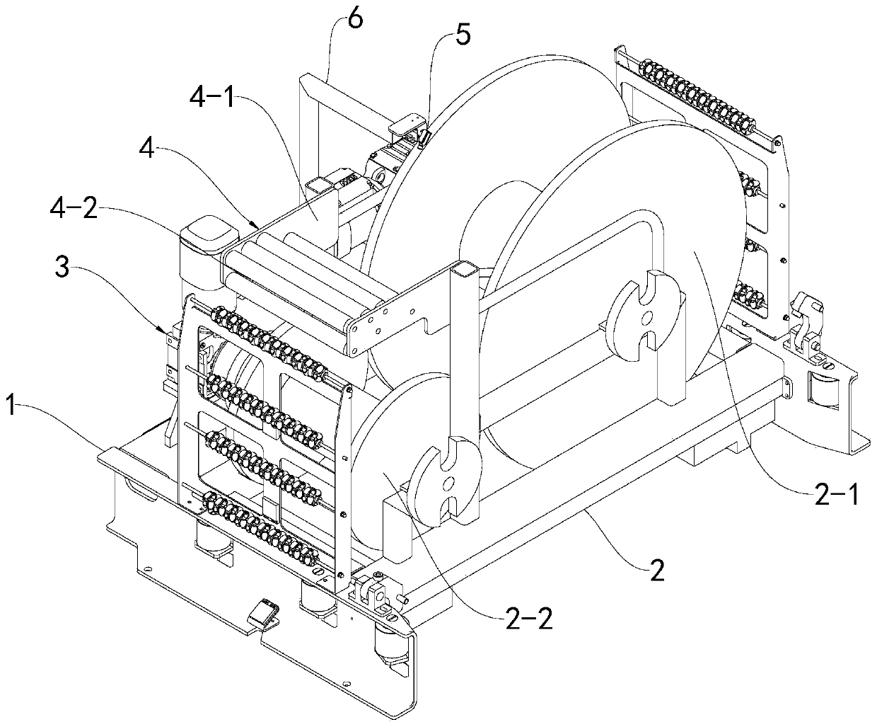
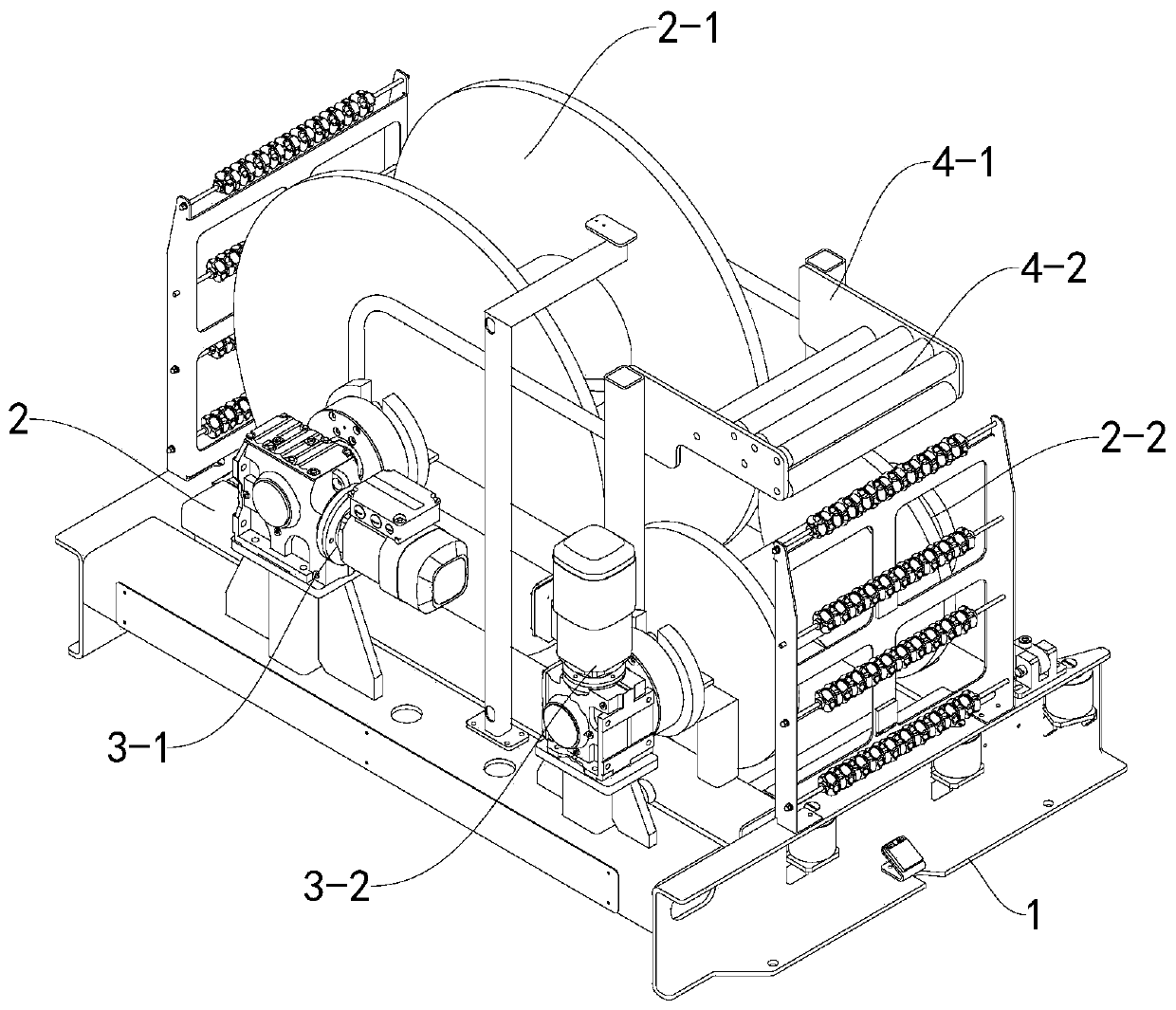
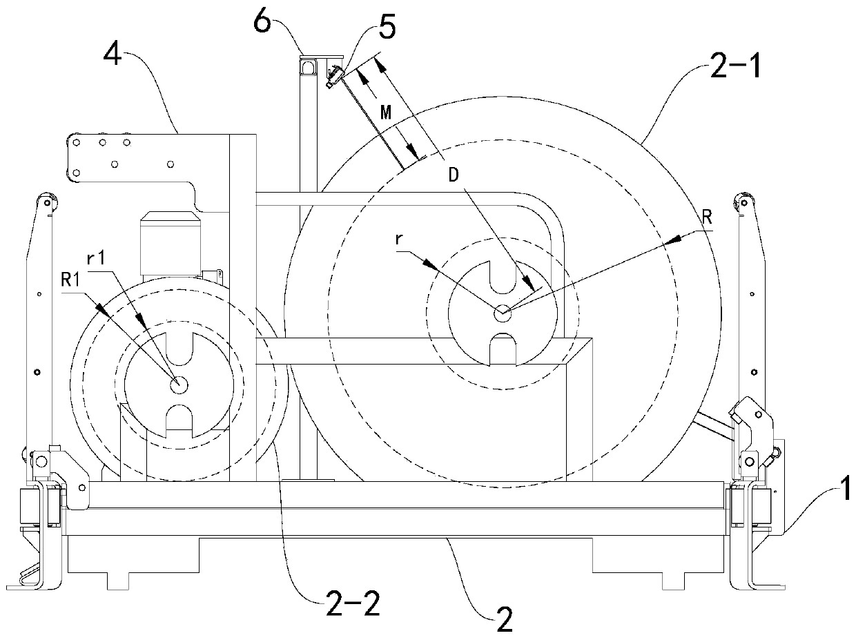
[0037] see Figure 1-2 , is a structural schematic diagram of an embodiment of the present invention, providing a material guide system, including a frame 1, a guide trolley 2, a driving mechanism 3, and a guide bracket 4, the guide trolley 2 is loaded on the frame 1, and the drive The mechanism 3 is installed on the frame 1 , and the decoupling bracket 4 is arranged on the decoupling trolley 2 . The guide trolley 2 includes a material roller 2-1 and a cloth cloth roller 2-2 supported thereon, the material roll...


PUM


Abstract

The invention discloses a material unwinding system and a material unwinding control method. The system comprises an unwinding trolley, a drive mechanism and an unwinding support. The unwinding trolley comprises a material roller and a mat cloth roller, wherein the material roller and the mat cloth roller are supported on the unwinding trolley in a rotating manner. The drive mechanism comprises amaterial unwinding motor connected with the material roller in a transmission manner, and a mat cloth rolling motor connected with the mat cloth roller in a transmission manner. The material unwindingsystem further comprises a distance measuring sensor and a control unit. The control unit can obtain the cumulative remaining thickness of materials wound around the material roller in real time based on measuring data of the distance measuring sensor, according to the material cumulative remaining thickness obtained in real time, the control unit can calculate the length of the materials currently wound around the material roller and the cumulative rolling thickness of mat cloth rolled on the mat cloth roller in real time, and according to the cumulative rolling thickness of the mat cloth rolled on the mat cloth roller, the control unit can control output torque of the mat cloth rolling motor. The system and the method can achieve constancy of tension of the mat cloth in the material unwinding process.

Description

technical field [0001] The invention relates to the technical field of tire building, in particular to a material guiding system and a material guiding control method. Background technique [0002] In the existing rubber tire manufacturing process, the roll-shaped materials that constitute the tire blank, such as the inner liner, ply, belt layer, tread layer, etc., need to be guided by the unwinding device and then sequentially transported, wound and bonded to the Forming drum. [0003] The existing guiding device includes a guiding motor, a hysteresis brake, a distance measuring photoelectric sensor, a material roller, a cloth cloth roller, etc., wherein the cloth cloth roller is used as a driving roller, and the material roller is used as a driven roller. The roller is connected by transmission, and the hysteresis brake is connected with the material roller. [0004] When the tire building equipment is in normal production, the motor is turned on according to the materia...

Claims


Application Information

Patent Timeline
Patent Type & Authority Applications(China)
IPC IPC(8): B29D30/26
CPCB29D30/0016B29D30/26B29D2030/0038
Inventor 邓宁宁崔润记
Owner SAFE RUN & HISCENT MACHINERY SUZHOU
Learn More