
Constant-pressure energy-saving system of blowing and suction type centralized cotton suction device

An energy-saving system, blowing and sucking technology, applied in textiles and papermaking, etc., can solve the problems of power and energy waste, troublesome device control, unfavorable use, etc.

Inactive Publication Date: 2021-11-19
江苏格罗瑞节能科技有限公司
View PDF7 Cites 0 Cited by
  • Summary
  • Abstract
  • Description
  • Claims
  • Application Information

AI Technical Summary

Problems solved by technology

[0003] The existing constant-voltage energy-saving system of the cotton suction device has certain disadvantages when it is used. First, during the operation process, the motor of the dust collection box is always running, but the actual suction time is very short, resulting in a large amount of waste of electric energy. It is not conducive to people's use. In addition, the control of the device is more troublesome, and it cannot perform energy-saving operations well, which has brought certain adverse effects on people's use. system

Method used

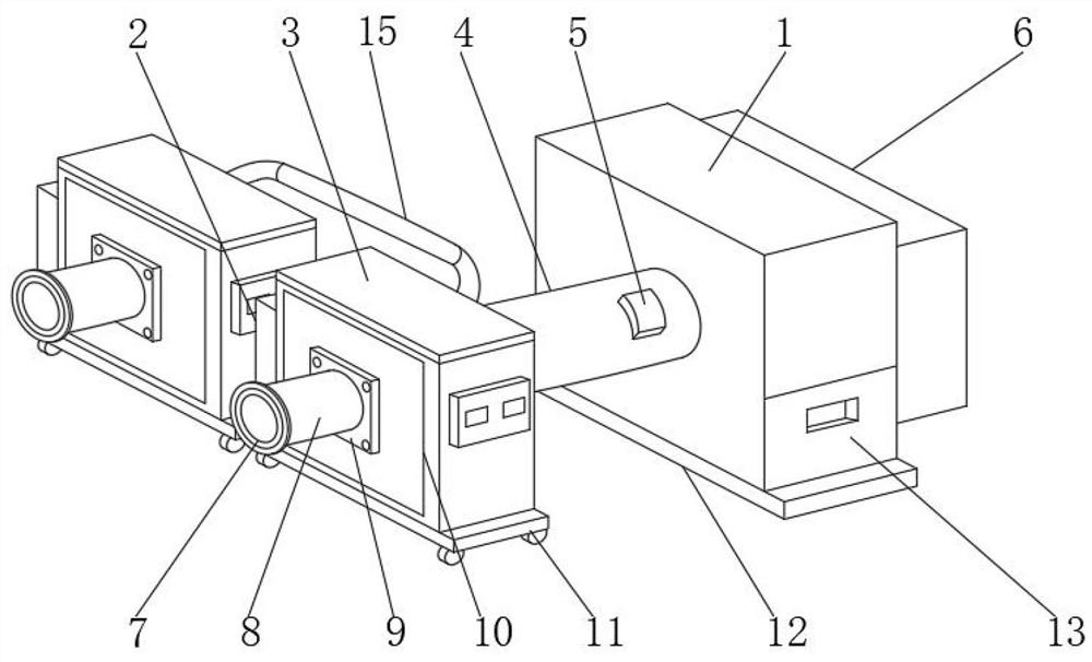

Image

  • Constant-pressure energy-saving system of blowing and suction type centralized cotton suction device
  • Constant-pressure energy-saving system of blowing and suction type centralized cotton suction device
  • Constant-pressure energy-saving system of blowing and suction type centralized cotton suction device

Examples


Embodiment 1

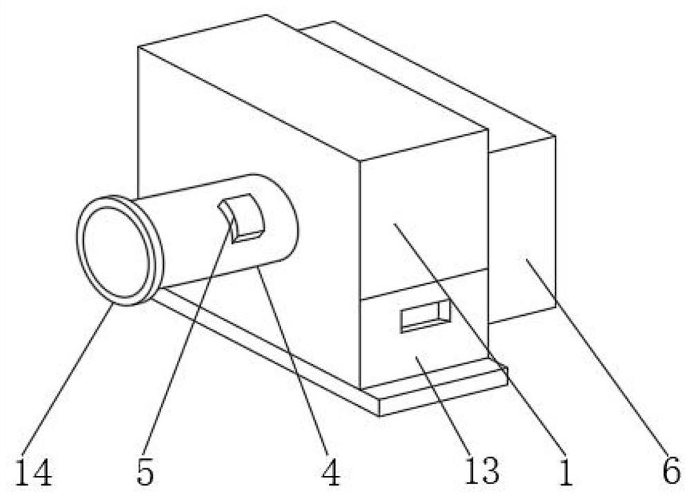
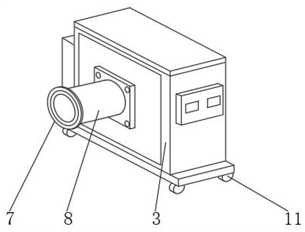
[0028] like Figure 1-3 As shown, the constant pressure energy-saving system of blowing and suctioning centralized cotton suction device includes centralized cotton suction box 1 and itinerant blowing and suction cleaning machine 3, and a cotton suction air duct 4 is installed between the centralized cotton suction box 1 and itinerant blowing and suction cleaning machine 3 With the connection mechanism 14, the rear end of the centralized cotton suction box 1 is equipped with a cotton suction motor 6, the bottom of the centralized cotton suction box 1 is equipped with a positioning base 12, and the outside of the centralized cotton suction box 1 is equipped with a cotton suction collection box 13, the suction The outer wall of the cotton air duct 4 is equipped with a motor drive control system 5 .

[0029] Further, the itinerant blowing and suction cleaning machine 3 is provided with 10-15 groups, and the outside of the itinerant blowing and suction cleaning machine 3 is equipp...

Embodiment 2

[0033] On the basis of Example 1, as Figure 1-6 As shown, the constant pressure energy-saving system of blowing and suctioning centralized cotton suction device includes centralized cotton suction box 1 and itinerant blowing and suction cleaning machine 3, and a cotton suction air duct 4 is installed between the centralized cotton suction box 1 and itinerant blowing and suction cleaning machine 3 With the connection mechanism 14, the rear end of the centralized cotton suction box 1 is equipped with a cotton suction motor 6, the bottom of the centralized cotton suction box 1 is equipped with a positioning base 12, and the outside of the centralized cotton suction box 1 is equipped with a cotton suction collection box 13, the suction The outer wall of the cotton air duct 4 is equipped with a motor drive control system 5 .

[0034] Further, the interior of the centralized cotton suction box 1 is provided with a circuit breaker, a power supply module, a fast fuse, a power supply ...

Embodiment 3

[0037] On the basis of Example 2, such as Figure 1-6 As shown, the constant pressure energy-saving system of blowing and suctioning centralized cotton suction device includes centralized cotton suction box 1 and itinerant blowing and suction cleaning machine 3, and a cotton suction air duct 4 is installed between the centralized cotton suction box 1 and itinerant blowing and suction cleaning machine 3 With the connection mechanism 14, the rear end of the centralized cotton suction box 1 is equipped with a cotton suction motor 6, the bottom of the centralized cotton suction box 1 is equipped with a positioning base 12, and the outside of the centralized cotton suction box 1 is equipped with a cotton suction collection box 13, the suction The outer wall of the cotton air duct 4 is equipped with a motor drive control system 5 .

[0038] Further, the motor drive control system 5 is equipped with a cleaning machine number detection module, a pressure sensor module, a communication...


PUM


Abstract

The invention discloses a constant-pressure energy-saving system of a blowing and suction type centralized cotton suction device. The system comprises a centralized cotton suction box and a circulating blowing and suction cleaning machine; a cotton suction air pipe and a connecting mechanism are installed between the centralized cotton suction box and the circulating blowing and suction cleaning machine; a cotton suction motor is installed at the rear end of the centralized cotton suction box; a positioning base is installed at the bottom of the centralized cotton suction box; a cotton suction and collection box body is installed on the outer side of the centralized cotton suction box; and a motor drive control system is installed on the outer wall of the cotton suction air pipe. According to the constant-pressure energy-saving system of the blowing and suction type centralized cotton suction device, the negative pressure change in a pipeline is detected through a pressure sensor, the number of cleaning machines connected with the cotton suction box is judged, the pressure in the pipeline is kept constant, the rotating speed of the motor is controlled in real time, and the air volume and the pressure are adjusted, so that the energy-saving effect is achieved; the running speed of the motor is controlled by the change condition of the negative pressure in the pipeline, so that the control is simple, and the energy-saving effect is more excellent; and cotton is sucked in a concentrated manner, so that the workload of workers is reduced.

Description

technical field [0001] The invention relates to the field of cotton suction devices, in particular to a constant pressure energy-saving system for a centralized cotton suction device with blowing and suction air. Background technique [0002] The constant pressure energy-saving system of the cotton suction device is a supporting device for energy-saving control of the cotton suction device. In the spinning workshop, it is necessary to use a touring blowing and suction cleaning machine and a dust collection box to form a cotton suction device to absorb and collect cotton materials in the workshop. With the continuous development of science and technology, people have higher and higher requirements for the manufacturing process of the constant pressure energy-saving system of the cotton suction device. [0003] The existing constant-voltage energy-saving system of the cotton suction device has certain disadvantages in use. First, during the operation process, the motor of the ...

Claims


Application Information

Patent Timeline
IPC IPC(8): D01H11/00
CPCD01H11/005D01H11/006
Inventor 葛陈鹏董淑棠赵永智蔡赟
Owner 江苏格罗瑞节能科技有限公司
Learn More