


Quick Research
Generate reliable direction feasibility study reports for your R&D in just a few steps.

Technical Q&A
Discover and master advanced knowledge NOW. Basics, ideas, possibilities, all at once.

Find Solutions
As an expert in R&D theories, this can generate solutions to your technical problems instantly.

Evaluate Feasibility
Analyze your overall solution with one click, know your potential R&D risks in advance.

Monitor Landscape
Get weekly tech updates, stay abreast of the latest tech innovations and key insights.
Carbon fiber static bed flue-gas desulfurization and denitrification technology and device
A desulfurization, denitrification, and carbon fiber technology, which can be used in combination devices, gas treatment, membrane technology, etc., to solve problems such as ecological damage, acid rain pollution, and carbon consumption, and achieve the effects of stable operation, low corrosion, and long service life.
- Summary
- Abstract
- Description
- Claims
- Application Information
AI Technical Summary
Problems solved by technology
Method used
Image

Examples
Embodiment 1
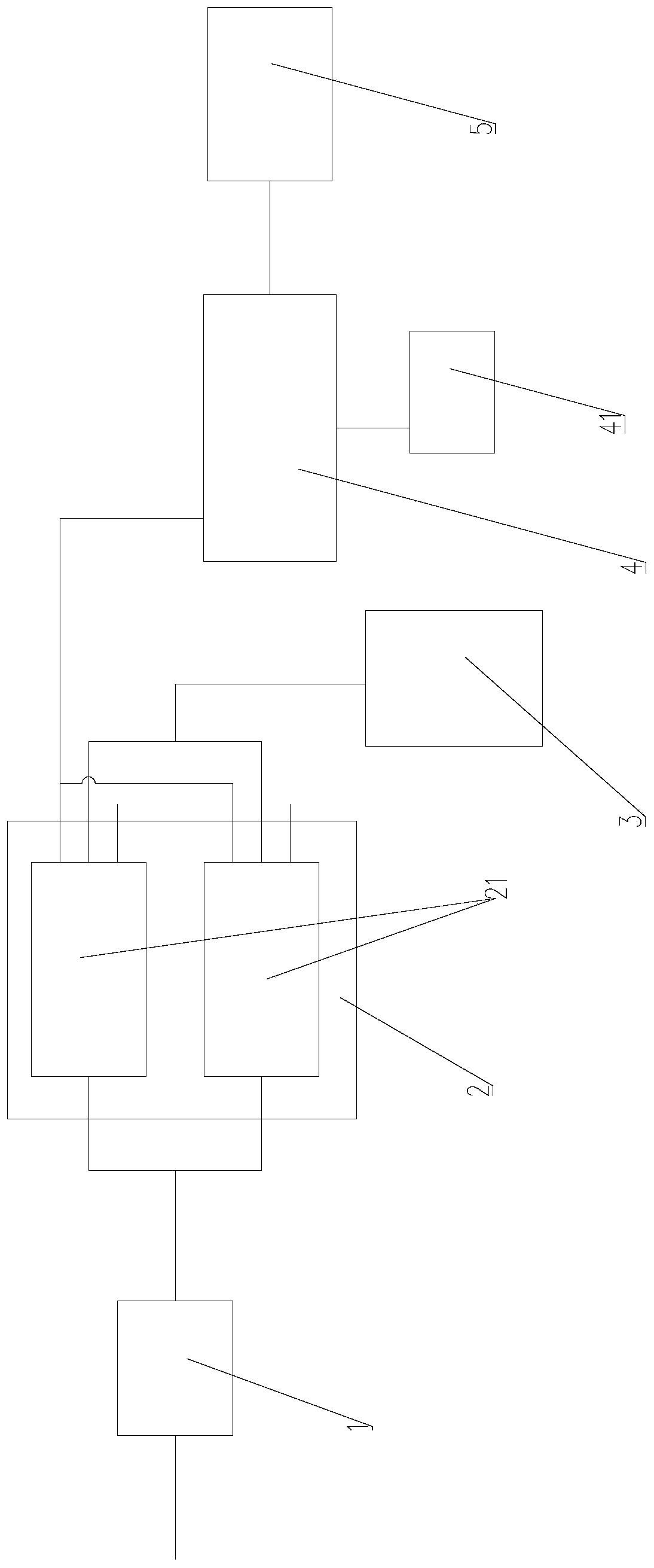
[0038] Please refer to figure 1 , The embodiment of the present invention provides a carbon fiber fixed bed flue gas desulfurization and denitrification device.
[0039] The carbon fiber fixed bed flue gas desulfurization and denitrification device includes a preprocessor 1, an adsorption reactor 2, a desorption device 3, a reduction device 4 and a SO 2 Adsorption device 5.
[0040] The flue gas enters from the upstream side of the desulfurization and denitrification device.
[0041] The preprocessor 1 is used to pretreat the flue gas, especially to remove most of the particulate matter in the flue gas, so as to improve the service life of the subsequent equipment and prolong the maintenance period of the subsequent equipment.
[0042] Therefore, the preprocessor 1 is a dust collector, preferably any one of an electrostatic precipitator, an electrostatic bag filter or a bag filter.
[0043] Described adsorption reactor 2 comprises at least two groups of switchable carbon fi...
Embodiment 2
[0052] Furthermore, the present invention also provides a carbon fiber fixed bed flue gas desulfurization and denitrification process, which is realized by relying on the carbon fiber fixed bed flue gas desulfurization and denitrification device described in the first embodiment.
[0053] The carbon fiber fixed bed flue gas desulfurization and denitrification process is carried out in the following steps:
[0054] (1) Pretreat the flue gas, which contains SO 2 , NO x ;
[0055] (2) Adsorb the flue gas through the carbon fiber fixed unit, and discharge the flue gas directly after the adsorption is completed;
[0056] (3) Desorption;
[0057] (4) Catalytic reduction of NO x ;
[0058] (5) Absorption of SO 2 .
[0059] Wherein, step (1) is mainly performed by the preprocessor of the device in the first embodiment. Remove the dust in the flue gas, so that the dust content in the flue gas is not more than 0.1g / Nm 3 .
[0060] Excessive dust content is not conducive to the...
PUM
 Abstract
Description
Claims
Application Information
 - R&D Engineer
- R&D Manager
- IP Professional
- Industry Leading Data Capabilities
- Powerful AI technology
- Patent DNA Extraction
Browse by: Latest US Patents, China's latest patents, Technical Efficacy Thesaurus, Application Domain, Technology Topic, Popular Technical Reports.
© 2024 PatSnap. All rights reserved.Legal|Privacy policy|Modern Slavery Act Transparency Statement|Sitemap|About US| Contact US: help@patsnap.com