
Pressure sensor having overpressure protection with reduced output error

A pressure sensor and sensor technology, applied in the direction of measuring fluid pressure through electromagnetic components, elastic deformation meter type fluid pressure measurement, measuring fluid pressure, etc., can solve the problems of sensor damage, unreliability, and expensive, etc., and achieve output error reduction Effect

Active Publication Date: 2019-10-25
HONEYWELL INT INC
View PDF8 Cites 1 Cited by
  • Summary
  • Abstract
  • Description
  • Claims
  • Application Information

AI Technical Summary

Problems solved by technology

[0010] While various overpressure protection mechanisms exist, some of these mechanisms result in small errors in the differential pressure measurement output from the pressure sensor
Others of these mechanisms are expensive to implement due to expensive machining operations
Furthermore, some of these mechanisms are unreliable under certain operating conditions and still allow sensor damage to occur

Method used


Image

  • Pressure sensor having overpressure protection with reduced output error
  • Pressure sensor having overpressure protection with reduced output error
  • Pressure sensor having overpressure protection with reduced output error

Examples


Embodiment Construction

[0024] Figure 1 to Figure 8 (discussed below) and the various embodiments used to describe the principles of the invention in this patent document are by way of illustration only and should not be construed as limiting the scope of the invention in any way. Those skilled in the art will understand that the principles of the invention may be implemented in any type of suitably arranged device or system.

[0025] figure 1 An exemplary industrial process control and automation system 100 according to the present disclosure is shown. Such as figure 1 As shown, system 100 includes various components that facilitate the production or processing of at least one product or other material. For example, system 100 may be used to facilitate control of components in one or more industrial plants. Each plant represents one or more processing facilities (or one or more portions thereof), such as one or more manufacturing facilities for producing at least one product or other material. ...


PUM


Abstract

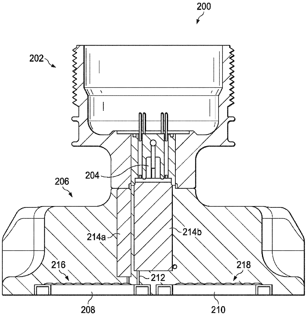
An apparatus includes a sensor body (206), a sensor (204) configured to measure differential pressure, and first and second pressure inputs in or on the sensor body. The pressure inputs are configuredto provide multiple input pressures to the sensor. Each pressure input includes a barrier diaphragm (208, 210) configured to move in response to pressure and an overload diaphragm (216, 218) configured to limit movement of the barrier diaphragm. The overload diaphragm is also configured to exert a preload force against the sensor body. The overload diaphragm of each pressure input may include multiple convolutions. Bases (502) of the convolutions may be configured to provide the preload force, and tops of the convolutions may be separated from the sensor body by gaps (504). Tops (602) of theconvolutions that are non-adjacent may be configured to provide the preload force, and tops of the convolutions between the non-adjacent convolutions may be separated from the sensor body by gaps (604).

Description

[0001] Cross-references and priority claims to related applications [0002] This patent application claims priority under 35 U.S.C. § 119(e) to the following U.S. Provisional Patent Application: [0003] - U.S. Provisional Patent Application 62 / 469,716 filed March 10, 2017; [0004] - U.S. Provisional Patent Application 62 / 469,954, filed March 10, 2017; [0005] - U.S. Provisional Patent Application 62 / 470,080, filed March 10, 2017; and [0006] - U.S. Provisional Patent Application 62 / 470,089 filed March 10, 2017. [0007] All of these provisional applications are hereby incorporated by reference in their entirety. technical field [0008] This disclosure generally relates to pressure sensors. More specifically, the present disclosure relates to pressure sensors with overvoltage protection with reduced output errors. Background technique [0009] Differential pressure transmitters typically operate by providing two pressure values ​​to the sensor. The sensor converts...

Claims


Application Information

Patent Timeline
Patent Type & Authority Applications(China)
IPC IPC(8): G01L19/06G01L19/14G01L7/08
CPCG01L9/0052G01L19/0046G01L19/14G01L19/0618G01L13/00G01L13/025
Inventor 乔治·赫尔歇理查德·D·道格特
Owner HONEYWELL INT INC
Learn More