
Modeling method of bed body fluid-heat-solid coupling finite element thermal characteristic analysis model

A technology of analysis model and modeling method, applied in special data processing applications, instruments, electrical digital data processing, etc., can solve problems such as low accuracy of heat transfer coefficient, large error, and failure to meet the thermal design analysis of the bed, and achieve construction The effect of clear thinking, high accuracy and high precision

Inactive Publication Date: 2019-10-25
XI AN JIAOTONG UNIV
View PDF2 Cites 6 Cited by
  • Summary
  • Abstract
  • Description
  • Claims
  • Application Information

AI Technical Summary

Problems solved by technology

In order to analyze the temperature distribution and thermal deformation of the bed under the comprehensive influence of internal and external heat sources such as coolant and ambient temperature, as well as the flow and heat transfer of the coolant on the bed, the existing method is to use the similarity criterion of heat transfer, and in a large number of On the basis of simplifying the assumed conditions, the flow of coolant on the bed is idealized as a fluid-sweeping flat plate model, and then the thermal characteristic analysis model of the bed is established based on the finite element method. The biggest defect of this method is that it uses the heat transfer similarity The accuracy of the heat transfer coefficient calculated by the criterion is low, and the error between the analysis results of the built thermal characteristic analysis model of the bed and the actual measured value is relatively large, which cannot meet the needs of accurate analysis of the thermal characteristics of the bed, let alone meet the requirements of the thermal characteristics of the bed. Demand for Design Analysis

Method used


Image

  • Modeling method of bed body fluid-heat-solid coupling finite element thermal characteristic analysis model
  • Modeling method of bed body fluid-heat-solid coupling finite element thermal characteristic analysis model
  • Modeling method of bed body fluid-heat-solid coupling finite element thermal characteristic analysis model

Examples


Embodiment Construction

[0032] The present invention will be described in further detail below in conjunction with the accompanying drawings.

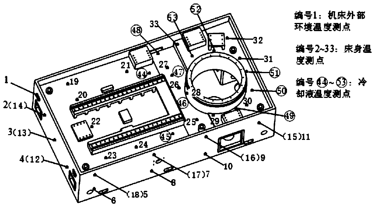
[0033] refer to figure 1 , a modeling method for bed flow-thermal-solid coupling finite element thermal characteristic analysis model, including the following steps:

[0034] 1) Combining the theoretical calculation and the surveying and mapping results of the actual coolant coverage under the grinding process, the real geometric model of the coolant is established on the basis of the geometric model of the bed, and the specific steps are as follows:

[0035] 1.1) In the 3D modeling software (Pro / E, Solidworks, etc.), establish the geometric model of the bed according to the actual size of the bed in order to improve the analysis efficiency; if there is a bed model, it needs to be simplified. The basic principles of simplification are: Delete shape structures and accessories that have little influence on thermal characteristic analysis and structural static ...


PUM


Abstract

The invention discloses a modeling method of a bed body fluid-heat-solid coupling finite element thermal characteristic analysis model. The method comprises the following steps: firstly, establishinga real geometric model of the cooling liquid in a flow channel of a lathe bed, and performing fluid simulation analysis on the flowing process of the cooling liquid in the lathe bed by using Ansys CFXsoftware and based on a finite element method on the basis of fully considering a flowing heat exchange boundary condition; secondly, tranmistting a heat exchange coefficient result obtained throughfluid analysis to a thermal analysis module by adopting a fluid-heat-solid multi-physical field sequential coupling analysis method, and meanwhile, solving temperature distribution of a lathe bed by considering other boundary conditions; and finally, loading the temperature of the lathe bed into the structural statics model, and finally solving the thermal deformation of the lathe bed. The methodhas good universality and can be used for thermal characteristic analysis of similar lathe beds or other equipment.

Description

technical field [0001] The invention belongs to the technical field of thermal analysis of a bed of a machine tool, and in particular relates to a modeling method for a fluid-thermal-solid coupling finite element thermal characteristic analysis model of a bed. Background technique [0002] Reducing the thermal error of the machine tool is one of the key issues to be solved urgently to improve the machining accuracy of the machine tool. As the key basic component of the precision machining machine tool, the main function of the bed is to carry and serve as a reference, support other parts and maintain the relationship between the parts. relative position. Due to the uneven temperature distribution of the bed under the comprehensive influence of internal and external heat sources, thermal deformation occurs, which directly destroys the design accuracy of key assembly surfaces, and ultimately leads to a reduction in the machining accuracy of the whole machine. Therefore, the te...

Claims


Application Information

Patent Timeline
IPC IPC(8): G06F17/50
CPCG06F30/20
Inventor 史晓军王维库穆英杰杨孝尹邦涛
Owner XI AN JIAOTONG UNIV
Learn More