Laser radar and detecting device thereof
A laser radar and detection device technology, applied in the field of distance measurement, can solve problems such as reducing the use efficiency, complex structure design of the detection device, and increasing the difficulty of laser radar
- Summary
- Abstract
- Description
- Claims
- Application Information
AI Technical Summary
Problems solved by technology
Method used
Image
Examples
Embodiment 1
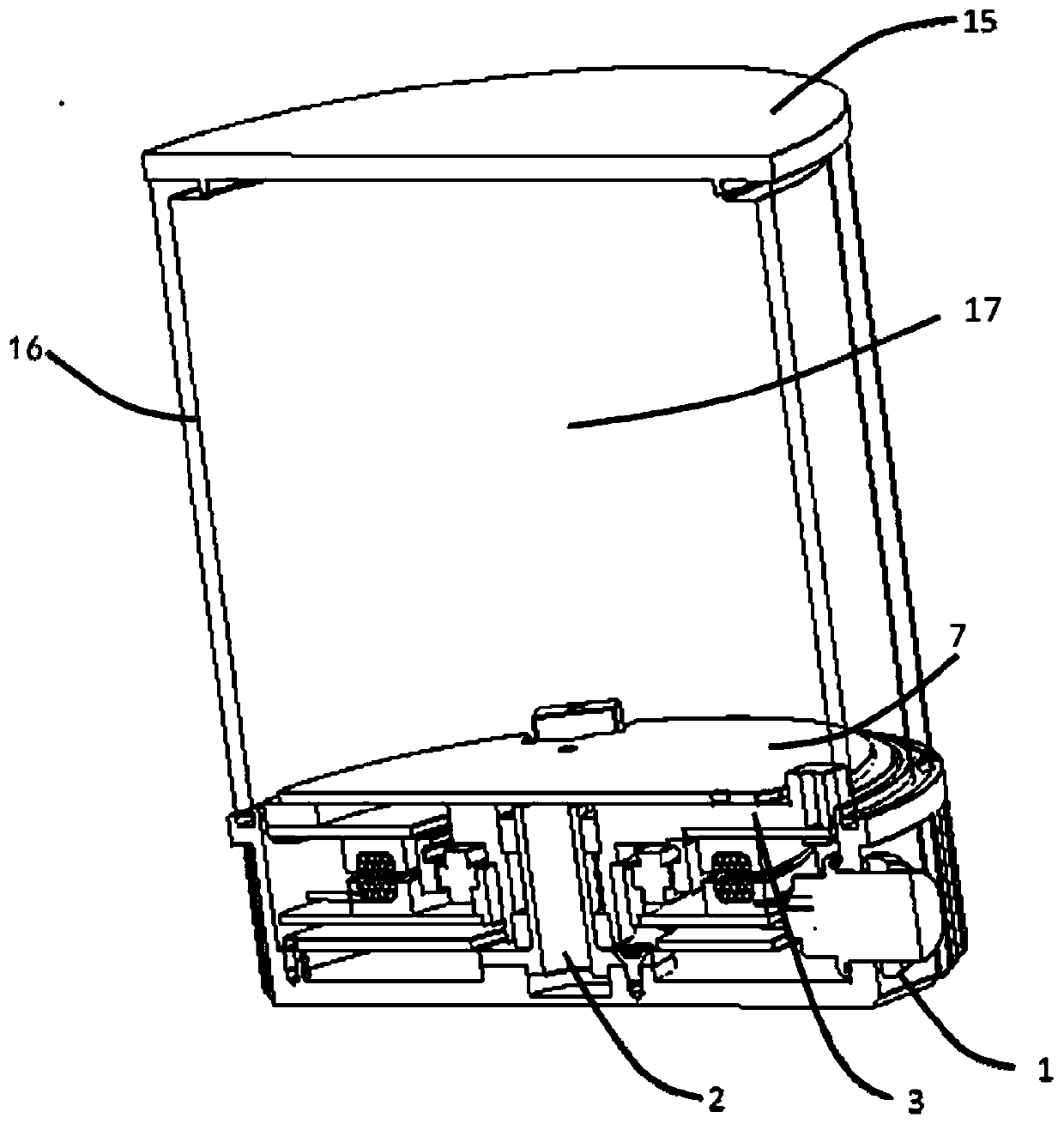
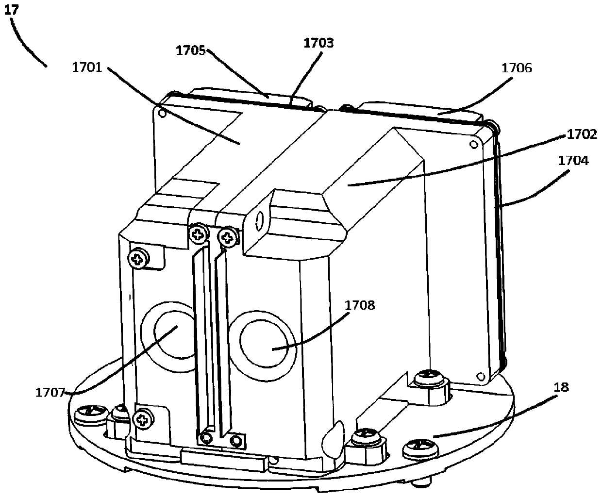
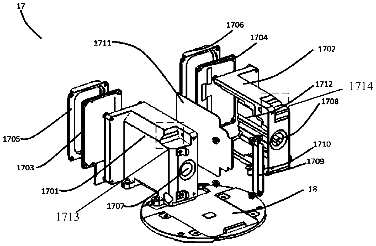
[0060] Embodiment 1 may include a laser radar detection device, including a lens barrel, a beam emitting device, a transmitting lens assembly, a receiving lens assembly, and a photoelectric processing device;
[0061] The lens barrel includes an emitting support body and a receiving support body, and the extending directions of the emitting support body and the receiving support body are parallel to each other;
[0062] The emitting lens assembly is located inside the emitting support and on the optical path of the detection beam emitted by the beam emitting device;
[0063] The receiving lens assembly is located inside the receiving support and on the optical path of the echo beam received by the photoelectric processing device.
Embodiment 2
[0064] Embodiment 2 may include the lidar detection device described in Embodiment 1, and the detection device further includes a light barrier, and the light barrier is arranged between the emitting support and the receiving support, and is parallel to the emitting support The extension direction of the body and the receiving support body.
Embodiment 3
[0065] Embodiment 3 may include the lidar detection device described in Embodiment 1 or 2, wherein the beam emitting device includes a emitting circuit board, and the emitting circuit board is located outside the emitting support body and arranged on the emitting The rear end of the support body, wherein the rear end of the emitting support body is the other end opposite to the end where the emitting support body emits the detection beam;
[0066] The photoelectric processing device includes a receiving circuit board, the receiving circuit board is located outside the receiving support body and arranged at the rear end of the receiving support body, wherein the rear end of the receiving support body is connected to the receiving support body The supporting body receives the echo beam at the other end opposite to one end.
PUM
 Abstract
Description
Claims
Application Information
 - Generate Ideas
- Intellectual Property
- Life Sciences
- Materials
- Tech Scout
- Unparalleled Data Quality
- Higher Quality Content
- 60% Fewer Hallucinations
Browse by: Latest US Patents, China's latest patents, Technical Efficacy Thesaurus, Application Domain, Technology Topic, Popular Technical Reports.
© 2025 PatSnap. All rights reserved.Legal|Privacy policy|Modern Slavery Act Transparency Statement|Sitemap|About US| Contact US: help@patsnap.com


