Soil retaining structure suitable for power building built on soft geology

A soil retaining structure and electric power technology, which is applied to buildings, underwater structures, infrastructure engineering, etc., can solve the problems of uncontrollable internal quality, long construction period, and prone to collapse, so as to achieve stable and controllable internal quality, cycle time Short, fast construction effect

Pending Publication Date: 2019-10-25
GUANGDONG POWER GRID CO LTD +1
View PDF0 Cites 3 Cited by
  • Summary
  • Abstract
  • Description
  • Claims
  • Application Information

AI Technical Summary

Problems solved by technology

[0004] ① An integral stress surface cannot be formed, the structure is unstable and prone to collapse;
[0005] ②Rubber is not easy to transport in mountainous and other road conditions;
[0006] ③ Manual masonry is required, the construction period is long, and the internal quality is uncontrollable;
[0007] ④Especially when the land is soft ground, the traditional retaining wall cannot sit on the foundation, and it is easy to tilt and collapse after a long time

Method used


Image

  • Soil retaining structure suitable for power building built on soft geology
  • Soil retaining structure suitable for power building built on soft geology

Examples


Embodiment 1

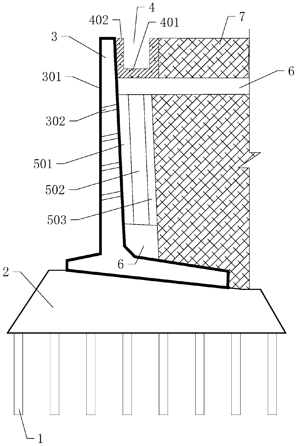
[0032] see figure 1 , this embodiment provides a soil retaining structure suitable for power buildings built on soft ground, used to cover backfill sandy soil 7 on the side of the power building, including a pile foundation reinforcement structure 1, a graded sandstone cushion layer 2 and retaining wall body 3. The graded sand cushion layer 2 is located above the pile foundation reinforcement structure 1 and gradually becomes thicker toward the power building; the retaining wall main body 3 is composed of cement and steel bars, and is located Above the stone mat cushion 2; the side of the retaining wall main body 3 close to the power building is a vertical surface structure 301 whose thickness gradually increases from top to bottom. Preferably, the power building can be a substation.

[0033] It can be understood that the pile foundation reinforcement structure 1 is set at the bottom as a supporting foundation to reduce the requirements of the main body of the retaining wall...

Embodiment 2

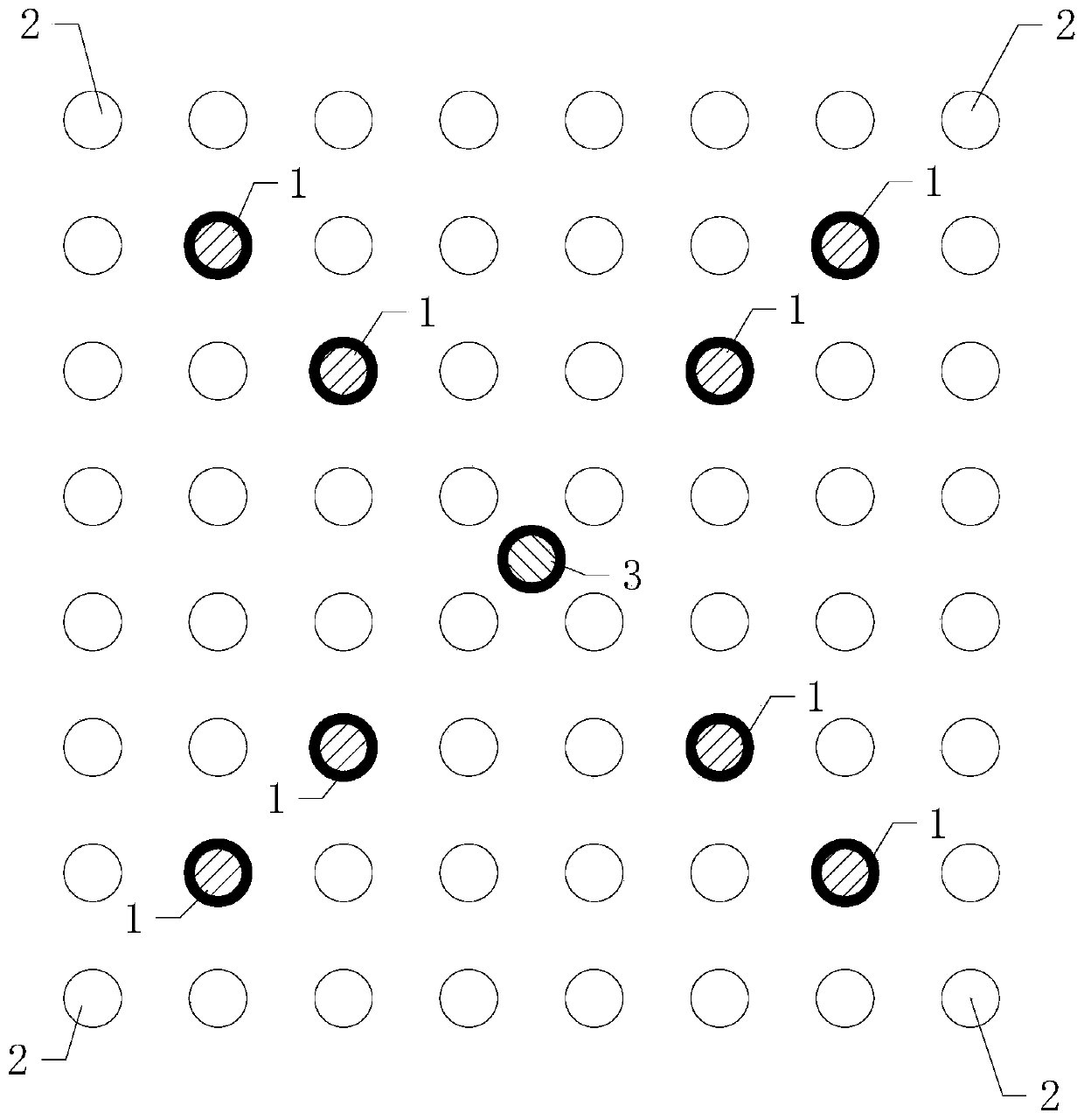
[0046] see figure 2 , this embodiment provides a pile foundation reinforcement structure suitable for Embodiment 1, including several pile foundation stations arranged in a square array, part or all of which are located on the pile foundation stations on the diagonal of the square array Each erection is provided with a peripheral jet grouting pile 1, and each of the remaining pile foundation stations is provided with a wooden pile 2.

[0047] It can be understood that the combination of the wooden pile 2 and the rotary grouting pile can not only ensure the stability of the foundation, but also reduce the economic cost.

[0048] Preferably, a central jet grouting pile 3 is provided at the intersection of two diagonal lines of the square array, and the number of the peripheral jet grouting piles 1 is an integer multiple of four. Further, every four peripheral jet grouting piles 1 can form four vertices of a regular quadrilateral. It can be understood that the regular quadrila...


PUM


Abstract

The invention relates to the technical field of power equipment, and particularly discloses a soil retaining structure suitable for a power building built on soft geology. The soil retaining structureis used for shielding backfilled sandy soil on the side surface of the power building. The soil retaining structure comprises a pile foundation reinforcing structure, a soil retaining structure suitable for a power building built on soft geology and a soil retaining wall main body. The pile foundation reinforcing structure comprises a plurality of wood piles and peripheral jet grouting piles which are arranged in a square array, and a central jet grouting pile is arranged at the central position of the square array; the graded sand stone cushion layer is located above the pile foundation reinforcing structure and gradually thickens towards the direction close to the power building; the soil retaining wall main body is composed of cement and steel bars and is located above the graded sandstone cushion layer; and the side, close to the power building, of the soil retaining wall main body is of a vertical surface structure, and the thickness of the soil retaining wall main body is gradually increased from top to bottom. The soil retaining structure is suitable for the power building built on soft geology, and has the advantages of being stable in structure, convenience to transportand the like.

Description

technical field [0001] The invention relates to the technical field of power equipment, in particular to a soil retaining structure suitable for power buildings built on soft ground. Background technique [0002] The southern part of our country is mostly mountainous and rainy in summer. When building transmission and distribution line towers, substations, substations and power distribution rooms in places with restricted terrain, accidents such as landslides are prone to occur. Generally, rubble is used to build a retaining wall to protect the above-mentioned electrical equipment. [0003] The retaining wall with traditional rubble structure has the following disadvantages: [0004] ① An integral stress surface cannot be formed, the structure is unstable and prone to collapse; [0005] ②Rubber is not easy to transport in mountainous and other road conditions; [0006] ③ Manual masonry is required, the construction period is long, and the internal quality is uncontrollabl...

Claims


Application Information

Patent Timeline
Patent Type & Authority Applications(China)
IPC IPC(8): E02D29/02E02D5/46
CPCE02D29/0225E02D29/0275E02D5/46
Inventor 唐小亮杨芳周亚兵
Owner GUANGDONG POWER GRID CO LTD
Why Eureka
Try Eureka