A bridge guardrail multi-angle cleaning machine

A multi-angle cleaning machine technology, applied in cleaning methods, road surface cleaning, construction, etc., can solve the problems of cleaning dead corners, affecting traffic, and unsafe manual cleaning of guardrails, etc., and achieves the effect of less space and small volume

Active Publication Date: 2020-11-27
JINAN JINYU HIGHWAY IND DEV
View PDF7 Cites 0 Cited by
  • Summary
  • Abstract
  • Description
  • Claims
  • Application Information

AI Technical Summary

Problems solved by technology

[0003] Manual cleaning of guardrails is labor-intensive, and the cleaning efficiency is low. During the day, there is a large traffic flow. Manual cleaning of guardrails is unsafe and affects traffic.
Ordinary cleaning equipment cannot clean the outside of the railings, and there are cleaning dead spots; the edges of bridge railings are often steps, and there is usually only a few meters of space on the steps, and it is difficult to place large-scale cleaning equipment on the edge of the road next to the railings

Method used


Image

  • A bridge guardrail multi-angle cleaning machine
  • A bridge guardrail multi-angle cleaning machine
  • A bridge guardrail multi-angle cleaning machine

Examples


Embodiment 1

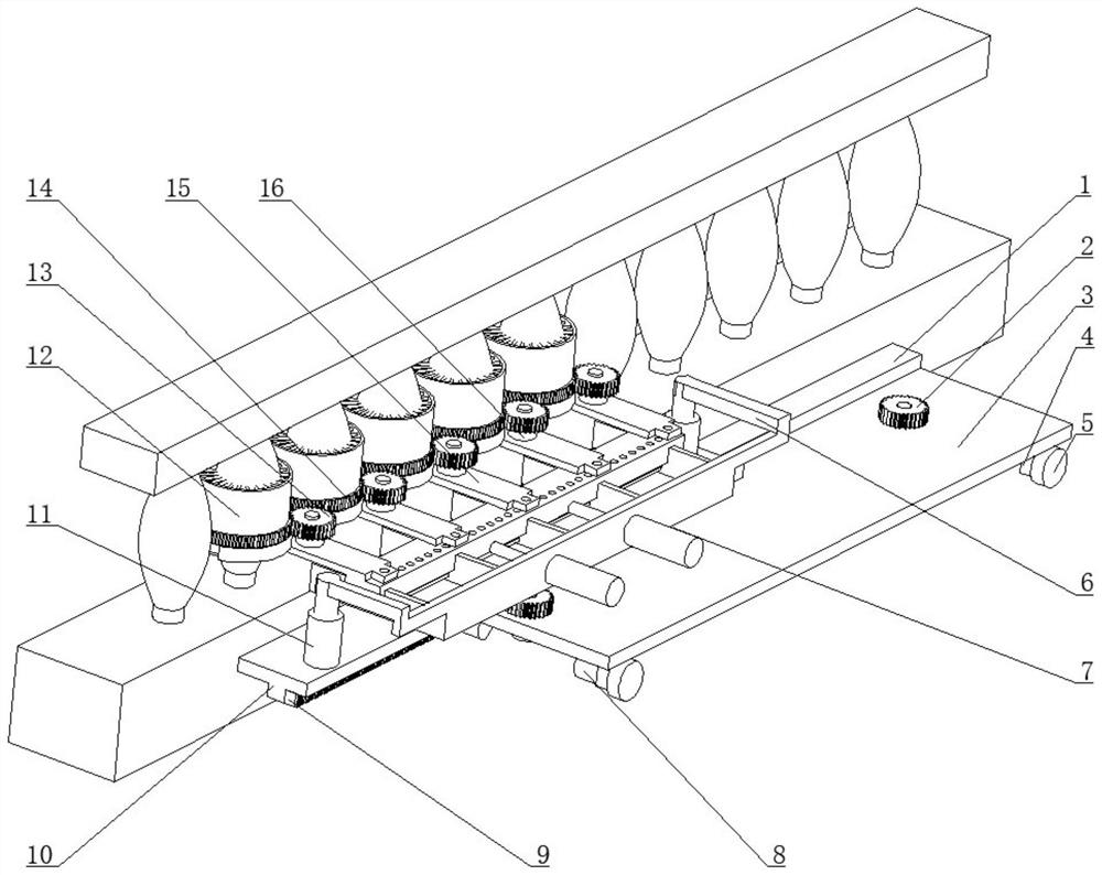
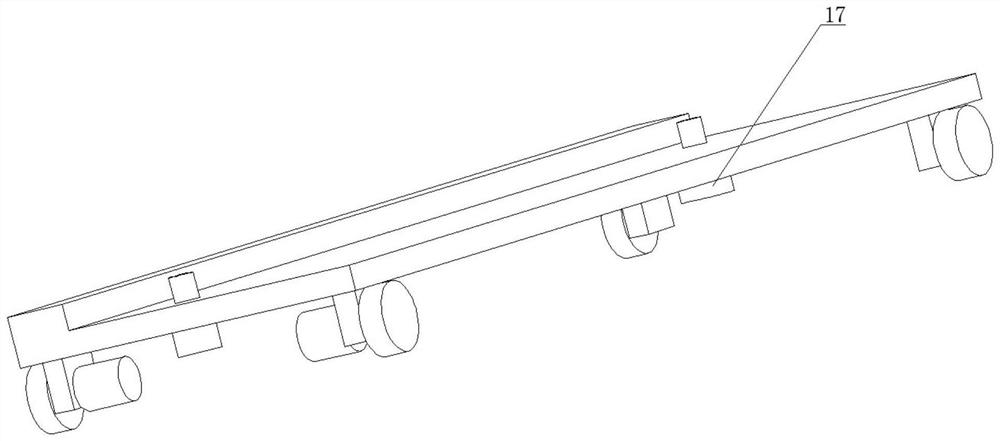
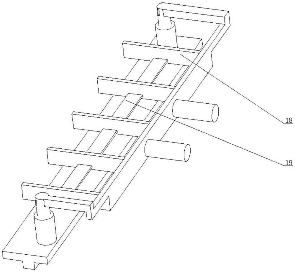
[0055] Embodiment 1: It is possible to clean one end of the bridge. Manually control the retraction of the electric push rod 17, and manually control the motor 18 to advance to the next position for automatic cleaning. Manually control the electric push rod 2 11 to drive the U-shaped rod 6 to move upwards, and then move in the opposite direction. Through related components, the cleaning mechanism is driven to move up and down reciprocatingly. At the same time, the motor 2 16 is turned on, and the motor 2 16 drives the gear 13 rotates, so that motor 2 16 controls one end of the half ring gear 14 to contact with gear 2 13 until the other end of the half ring gear 14 contacts with gear 2 13, then turn on motor 2 16 in reverse to make gear 2 13 reverse again With the same number of turns, the hairbrush 24 moves up and down while reciprocating rotation through related components, and the hairbrush 24 wipes the bridge guardrail, realizing semi-automatic cleaning.

Embodiment 2

[0056] Embodiment 2: The controller controls the motor 8 and the motor 17 to cooperate to keep the cleaning mechanism still relative to the railing. The controller records the moving distance of the electric push rod 1 7, the movement of the electric push rod 2 11, and the rotation of the motor 2 16 And motor three 17 rotation situations, and control corresponding electric push rod one 7, electric push rod two 11, motor two 16 and motor three 17 in order. Make the electric push rod one 7 reciprocatingly move back and forth, and the electric push rod two 11 reciprocate up and down to realize the reciprocating up and down movement and forward and backward movement of the cleaning mechanism. The controller controls the rotation of the motor two 16, thereby realizing the reciprocating rotation of the brush 24, and The brush 24 reciprocates and moves up and down while reciprocating rotation, and the hairbrush 24 wipes the bridge guardrail, and realizes fully automatic at last.


PUM


Abstract

The invention relates to the field of cleaning equipment, in particular to a bridge guardrail multi-angle cleaning machine, and discloses a bridge guardrail multi-angle cleaning machine which comprises a bottom plate. The machine is characterized in that the two ends of the two sides of the bottom plate are respectively and fixedly connected with a vertical plate, one end of the upper side of thebottom plate is fixedly connected with a first square rod, the lower part of each vertical plate is respectively hinged with wheels, one set of symmetrical vertical plates are respectively and fixedlyconnected with a first motor, output shafts of the symmetrical first motors respectively penetrate through the vertical plates, output shafts of the symmetrical first motors are respectively and fixedly connected with the corresponding wheels, a moving mechanism is arranged on the upper side of the bottom plate, and a cleaning mechanism is arranged on the upper side of the bottom plate. Multi-angle cleaning of a bridge guardrail is facilitated.

Description

technical field [0001] The invention relates to the field of cleaning equipment, in particular to a bridge guardrail multi-angle cleaning machine. Background technique [0002] The urban population and vehicles are increasing year by year, and there are great contradictions between people, vehicles and road traffic. Guardrails are installed in almost all congested roads. The isolation guardrails are often dirty after being exposed to the sun and rain, which not only affects the appearance of the road The neat and beautiful, and the guardrail itself is easy to wear and tear. Bridge guardrails need to be cleaned regularly. [0003] Manual cleaning of guardrails is labor-intensive, and the cleaning efficiency is low. During the day, there is a large traffic flow. Manual cleaning of guardrails is unsafe and affects traffic. Ordinary cleaning equipment cannot clean the outside of the railings, and there are dead spots for cleaning; the edges of bridge railings are often steps, ...

Claims


Application Information

Patent Timeline
Patent Type & Authority Patents(China)
IPC IPC(8): E01H1/00
CPCE01H1/005
Inventor 李景军李少祯徐永利张实言
Owner JINAN JINYU HIGHWAY IND DEV
Why Eureka
Try Eureka