Buffer spring production process
A buffer spring and production process technology, applied in the field of parts processing, can solve the problems of difficulty in achieving fatigue resistance, wave spring deformation, complex stress, etc., and achieve the effects of good heating, reducing heat energy waste, and good thermal conductivity.
- Summary
- Abstract
- Description
- Claims
- Application Information
AI Technical Summary
Problems solved by technology
Method used
Image

Examples
Embodiment 1
[0031] A buffer spring production process, comprising the following steps:
[0032] A. Shot peening
[0033] Shot blasting is performed on the raw material (annular hard steel plate), specifically, cast steel shot is used for shot blasting.
[0034] B. The first suppression
[0035] The raw material is pressed for the first time by using a pressure forming machine with a pressure of 6-7MPa to obtain a preliminary formed buffer spring.
[0036] C, the first tempering
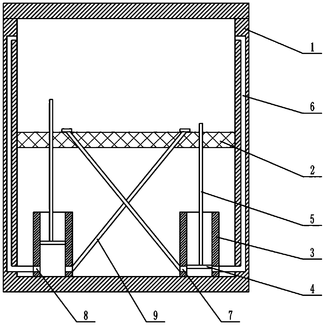
[0037] Put the formed buffer spring into the tempering furnace for tempering. The tempering furnace is located directly below the pressure forming machine. The upper end of the tempering furnace is provided with a closable opening. Specifically, the upper end of the tempering furnace is horizontally slid and connected with a baffle. The plate can turn the tempering furnace on or off. combine figure 1 As shown, the tempering furnace 1 is vertically slidably connected with a placement plate 2, and the placemen...
Embodiment 2
[0049] In this embodiment, three times of pressing and three times of tempering are carried out, and the rest of the steps are consistent with Embodiment 1.
[0050] The parameters of three times of pressing and three times of tempering are as follows:
[0051] Compression pressure (MPa) Tempering temperature (℃) Tempering time (min) the first time 6 350 50 the second time 7 400 80 the third time 8 450 100
Embodiment 3
[0053] In this embodiment, four times of pressing and four times of tempering are carried out, and the rest of the steps are consistent with Embodiment 1.
[0054] The parameters of four times of pressing and four times of tempering are as follows:
[0055] Compression pressure (MPa) Tempering temperature (℃) Tempering time (min) the first time 5 350 50 the second time 6 280 70 the third time 7 420 85 the fourth time 8 450 100
[0056] Carry out anti-fatigue test to the buffer spring that embodiment 1-3 produces, through test, the fatigue limit of the buffer spring that embodiment 1 processes can reach 1050MPa, the fatigue limit of the buffer spring that embodiment 2 processes can reach 1120MPa, implement The fatigue limit of the buffer spring processed by example 3 can reach 1130MPa. By test results, it is found that the fatigue limit of the buffer spring processed by embodiment 3 does not significantly increase compared wit...
PUM
| Property | Measurement | Unit |
|---|---|---|
| fatigue limit | aaaaa | aaaaa |
| fatigue limit | aaaaa | aaaaa |
| fatigue limit | aaaaa | aaaaa |
Abstract
Description
Claims
Application Information
 - Generate Ideas
- Intellectual Property
- Life Sciences
- Materials
- Tech Scout
- Unparalleled Data Quality
- Higher Quality Content
- 60% Fewer Hallucinations
Browse by: Latest US Patents, China's latest patents, Technical Efficacy Thesaurus, Application Domain, Technology Topic, Popular Technical Reports.
© 2025 PatSnap. All rights reserved.Legal|Privacy policy|Modern Slavery Act Transparency Statement|Sitemap|About US| Contact US: help@patsnap.com