Ophthalmic injection and extraction device

An extraction device and ophthalmology technology, applied in ophthalmic surgery, etc., can solve the problems of unsteady installation of needles and insecure installation of rubber stoppers, and achieve the effect of avoiding insecure installation and stable installation

Inactive Publication Date: 2019-10-25
赵玉新
View PDF0 Cites 1 Cited by
  • Summary
  • Abstract
  • Description
  • Claims
  • Application Information

AI Technical Summary

Problems solved by technology

[0004] The purpose of the present invention is to solve the shortcomings of the prior art that the installation of the rubber stopper is not firm and the needle cannot be stably installed, and proposes an ophthalmic injection extraction device

Method used


Image

  • Ophthalmic injection and extraction device
  • Ophthalmic injection and extraction device
  • Ophthalmic injection and extraction device

Examples


Embodiment 1

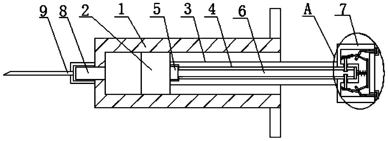
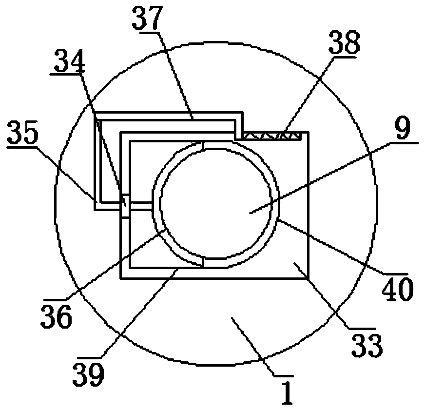
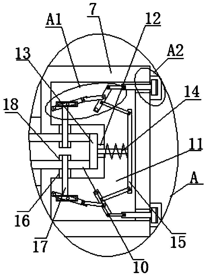
[0027] Reference Figure 1-5 , An ophthalmic injection extraction device, comprising a needle tube 1, a rubber stopper 2 is arranged in the needle tube 1, a pulling rod 3 is installed on one side of the rubber stopper 2, a pulling block 7 is arranged at one end of the pulling rod 3, and a side of the needle tube 1 is arranged There is an injection tube 8, a needle 9 is movably sleeved on the injection tube 8, a splint 33 is sleeved on the needle 9, a T-shaped hole 4 is opened on the pulling rod 3, and a connecting block 5 is fixedly installed on one side of the rubber stopper 2. A connecting rod 6 is fixedly installed on one side of the block 5, a connecting groove 10 is opened on one side of the pulling block 7, one end of the connecting rod 6 extends into the connecting groove 10, and a U-shaped cavity 11 is opened on the pulling block 7 through an inserting rod. 17 is inserted into the slot 18 to complete the installation of the rubber plug 2. Compared with the traditional c...

Embodiment 2

[0038] Reference Figure 1-5 , An ophthalmic injection extraction device, comprising a needle tube 1, a rubber stopper 2 is arranged in the needle tube 1, a pulling rod 3 is installed on one side of the rubber stopper 2, a pulling block 7 is arranged at one end of the pulling rod 3, and a side of the needle tube 1 is arranged There is an injection tube 8, a needle 9 is movably sleeved on the injection tube 8, a splint 33 is sleeved on the needle 9, a T-shaped hole 4 is opened on the pulling rod 3, and a connecting block 5 is fixedly installed on one side of the rubber plug 2 by welding , One side of the connecting block 5 is fixedly installed with a connecting rod 6 by welding, one side of the pulling block 7 is provided with a connecting groove 10, one end of the connecting rod 6 extends into the connecting groove 10, and a U-shaped cavity 11 is opened on the pulling block 7 , The insertion rod 17 is inserted into the slot 18 to complete the installation of the rubber plug 2. ...


PUM


Abstract

The invention belongs to the field of ophthalmology, and particularly relates to an ophthalmic injection and extraction device, aiming to solve the problems that existing rubber plugs are not mountedfirmly and syringe needles cannot be fastened. The ophthalmic injection and extraction device comprises a needle tube. A rubber plug is arranged in the needle tube. A pull rod is mounted on one side of the rubber plug, and a pull block is arranged at one end of the pull rod. An injection tube is arranged on one side of the needle tube, and a syringe needle movably sleeves the injection tube. A clamping plate sleeves the syringe needle, and a T-shaped hole is formed in the pull rod. A connection block is fixedly mounted on one side of the rubber plug, a connection rod is fixedly mounted on oneside of the connection block, and a connection groove is formed in one side of the pull block. The ophthalmic injection and extraction device has the advantages that an insertion rod is inserted intoa slot to complete mounting of the rubber plug, and the insertion mode can make the rubber plug mounted more firmly than conventional clamping modes; the syringe needle is clamped by an arc-shaped plate, unstable mounting of the syringe needle can be avoided, and people's demands are met.

Description

Technical field [0001] The invention relates to the technical field of ophthalmology, in particular to an ophthalmic injection extraction device. Background technique [0002] The full name of Ophthalmology is "Ophthalmology Specialty", which is a discipline that studies diseases that occur in the visual system, including the eyeball and its associated tissues. Ophthalmology generally studies vitreous, retinal diseases, ophthalmology, glaucoma and optic neuropathy, cataracts and many other subjects. Eye diseases. [0003] Generally, the injection extraction device refers to a commonly used syringe. However, in the prior art, the rubber stopper in the syringe is mostly installed by means of snapping. This causes the rubber stopper and the pulling rod to be separated easily if improper force is applied, and then As a result, the syringe is scrapped, and the needle is mostly directly sleeved on the injection tube. If the installation is not in place, pushing the pull rod to drive the...

Claims


Application Information

Patent Timeline
Patent Type & Authority Applications(China)
IPC IPC(8): A61F9/007
CPCA61F9/00736
Inventor 赵玉新王昭霞田霞
Owner 赵玉新
Why Eureka
Try Eureka