
Resinous tube member, method for manufacturing resinous tube member, resinous tube fitting, and resinous piping

A manufacturing method and resin technology are applied in the fields of resin-made pipe members, resin-made pipe members, resin-made pipe joints and resin-made pipes, which can solve the problems of narrowing, flow rate reduction, liquid accumulation, etc., so as to suppress internal convexity forming effect

Active Publication Date: 2019-10-22
MIRAIAL CO LTD
View PDF6 Cites 0 Cited by
  • Summary
  • Abstract
  • Description
  • Claims
  • Application Information

AI Technical Summary

Problems solved by technology

In addition, since the inner diameter of the pipeline is partially narrowed by the inner protrusion formed on the inner surface of the welded part of the pipe, there is a problem that when the liquid flows, the liquid accumulates there and causes the flow rate to decrease.

Method used


Image

  • Resinous tube member, method for manufacturing resinous tube member, resinous tube fitting, and resinous piping
  • Resinous tube member, method for manufacturing resinous tube member, resinous tube fitting, and resinous piping
  • Resinous tube member, method for manufacturing resinous tube member, resinous tube fitting, and resinous piping

Examples


Embodiment

[0069] Next, the resin pipe member of the present invention was manufactured as a trial, and its performance was confirmed, which will be described below. However, the description here is for the purpose of simple illustration, and is not intended to be limited thereto.

[0070] As a comparative example, such as Figure 7 As shown in part (a) of the above, two resin pipe members are produced, and the outer cylinder is fixed to the pipe body by welding so that the end faces of the outer cylinder are positioned on substantially the same plane so that there is no difference in the inner surface. the outer peripheral side.

[0071] The resin pipe members are welded and connected so as to face each other at their ends. Here, the heating time at the time of edge welding was 80 seconds (sec), and the pressing amount was 1.0 mm. After confirming the connection part after welding the end, the result is as follows Figure 7 As shown in part (b) of , an inner protrusion with a size o...


PUM

PropertyMeasurementUnit
heightaaaaaaaaaa
lengthaaaaaaaaaa

Abstract

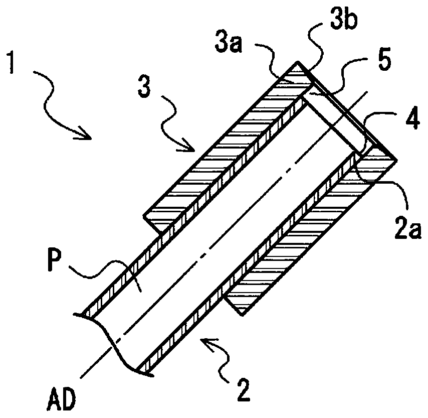
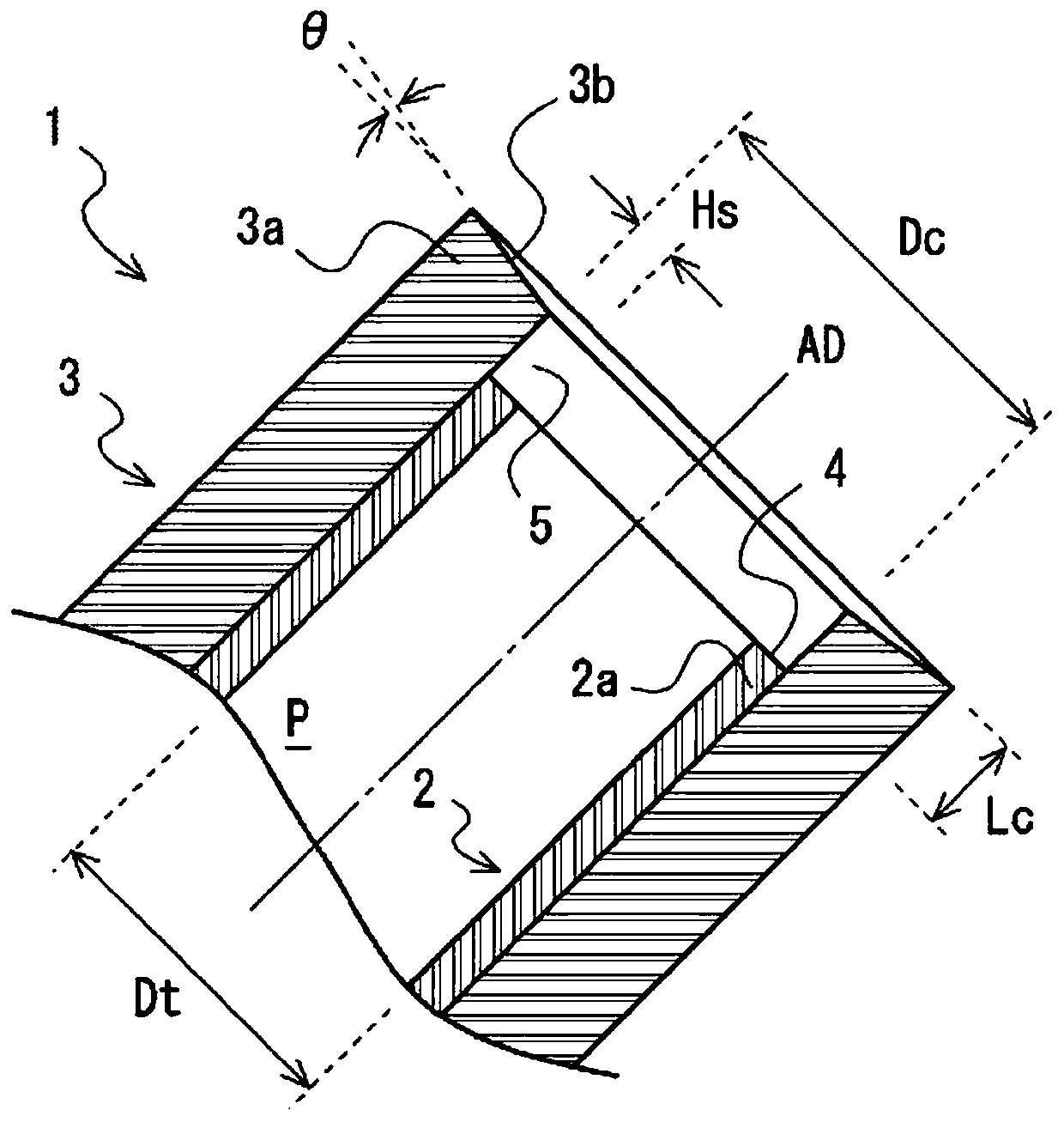
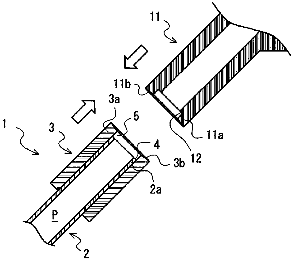
A resinous tube member (1) according to the present invention comprises: a tube body (2) having an internal flow path (P) in which a fluid flows; and an outer cylinder (3) that is arranged so as to cover the periphery of at least a body end (2a) of the tube body (2) on an outer peripheral side of the tube body (2), and that is fixed or adhered to the tube body (2). An outer cylinder end (3a) to bewelded to an end of another resinous tube member or a resinous tube fitting is positioned so as to protrude outward in an axis direction (AD) from the body end (2a) on an inner peripheral side thereof, and an inner face step (4) formed by an inner face of the outer cylinder end (3a) and an inner face of the body end (2a) is provided.

Description

technical field [0001] The present invention relates to a resin pipe member having an internal flow path through which a fluid flows and is connected to a resin pipe joint or other resin pipe members by welding the ends, and a method for manufacturing the resin pipe member. In particular, resin pipe joints and resin pipes propose a technique for effectively suppressing so-called indentation that may occur when a resin pipe member and a resin pipe joint or other resin pipe members are welded at their ends. Background technique [0002] Resin pipes such as chemical liquid delivery lines used in various industries are sometimes manufactured by using a fusion machine to connect the ends of resin pipe joints or resin pipe members made of thermoplastic resin or the like to each other. Manufactured by ground welding. [0003] To describe an example of the manufacturing method of such a resin pipe in detail, for example, in each of the paired jigs of a welding machine, each of two ...

Claims


Application Information

Patent Timeline
Patent Type & Authority Applications(China)
IPC IPC(8): B29C45/14
CPCB29C45/14
Inventor 溜渕晴也枝村洋一
Owner MIRAIAL CO LTD
Learn More