A steel-wood hybrid connection structure

A mixed connection, steel-wood technology, applied in building construction, construction, etc., can solve the problems of low shear stiffness of self-tapping screws, failure to meet the requirements of bearing capacity, and screws are easy to be pulled out, etc., to expand the stress-bearing area of ​​wood , Convenience in construction, Improve the effect of shear bearing capacity

Active Publication Date: 2021-08-10
SOUTHEAST UNIV
View PDF0 Cites 0 Cited by
  • Summary
  • Abstract
  • Description
  • Claims
  • Application Information

AI Technical Summary

Problems solved by technology

However, the traditional connection method of drilling self-tapping screws into the vertical wood surface has the following problems: (1) The drilling depth of self-tapping screws is limited by the thickness of the wood board, and the drilling depth of self-tapping screws has a great influence on the strength of the connection. When it is thin, it cannot meet the bearing capacity requirements; (2) The shear stiffness of the self-tapping screw connection is low, and when a large slip occurs, the screw is easy to be pulled out; (3) When the steel beam is a commonly used equilateral H-shaped steel When it is blocked by the lower flange of the H-shaped steel, the operating space is limited. When the beam height is low, it is not easy to construct

Method used


Image

  • A steel-wood hybrid connection structure
  • A steel-wood hybrid connection structure
  • A steel-wood hybrid connection structure

Examples


Embodiment 1

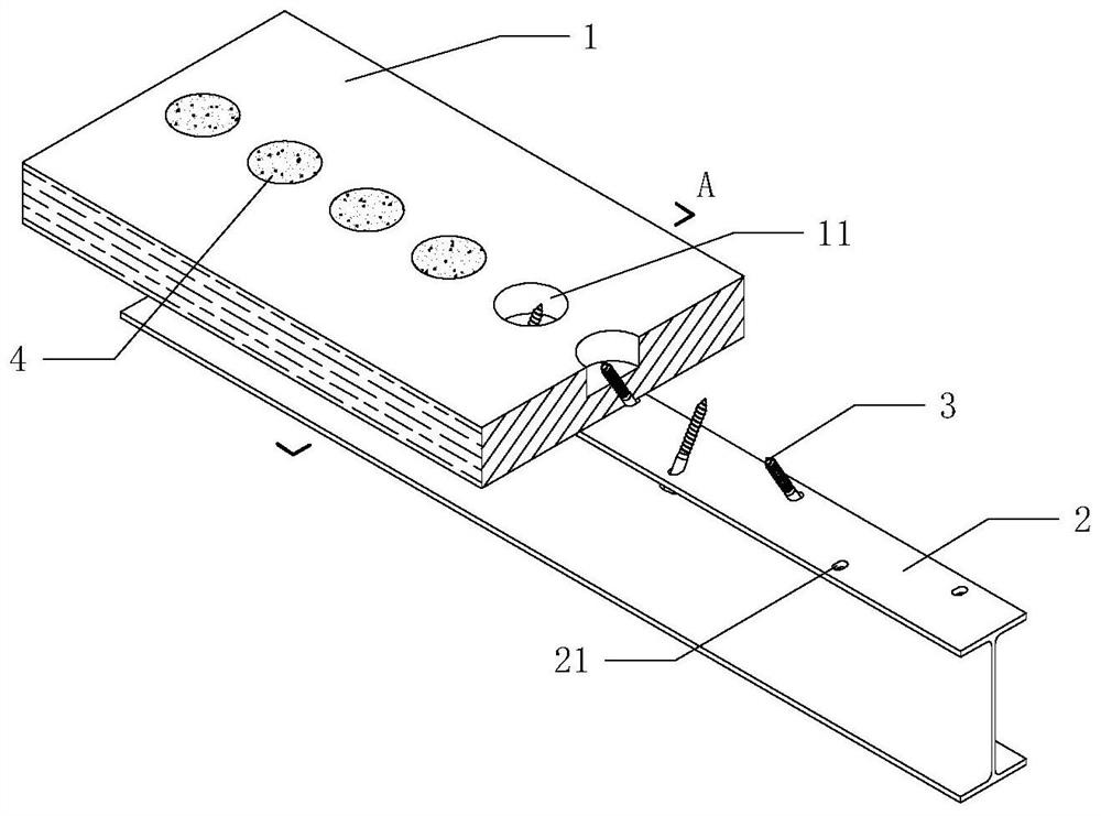
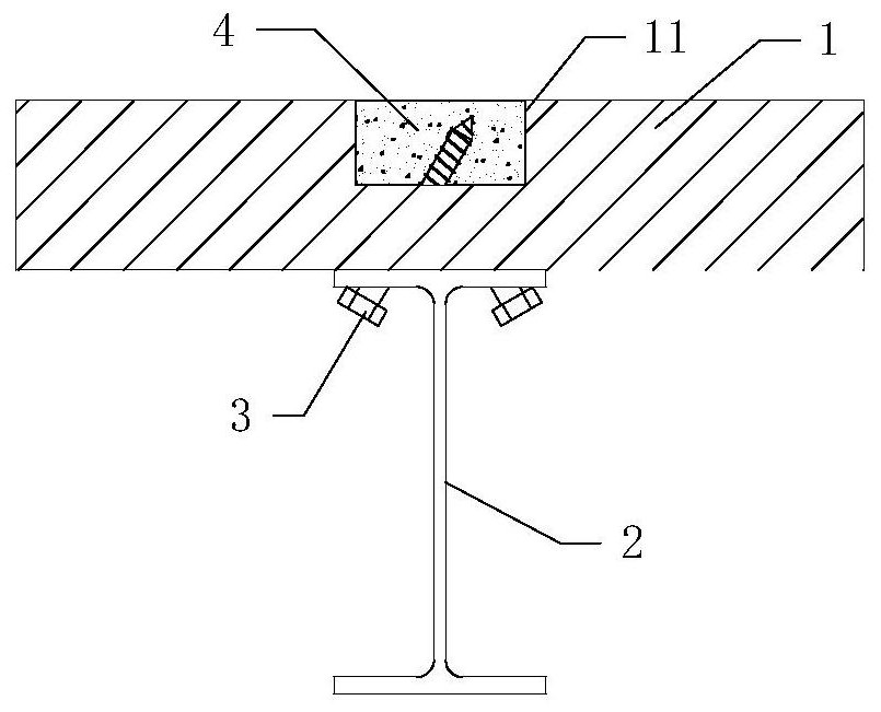
[0029] Such as Figure 1~2 , a cylindrical slot 11 is reserved on the upper surface of the plank 1, the depth of the slot 11 is 0.5 times the thickness of the plank 1, the steel member 2 is H-shaped steel, a long slot-shaped reserved hole 21 is reserved on the flange, and self-tapping screws 3 and the flange of the steel member 2 are screwed obliquely at a staggered angle, and arranged symmetrically and staggered on both sides of the symmetry axis of the section of the steel member 2. After the self-tapping screw 3 is installed, pour mortar into the slot 11 of the wooden board 1 4 and smooth.

Embodiment 2

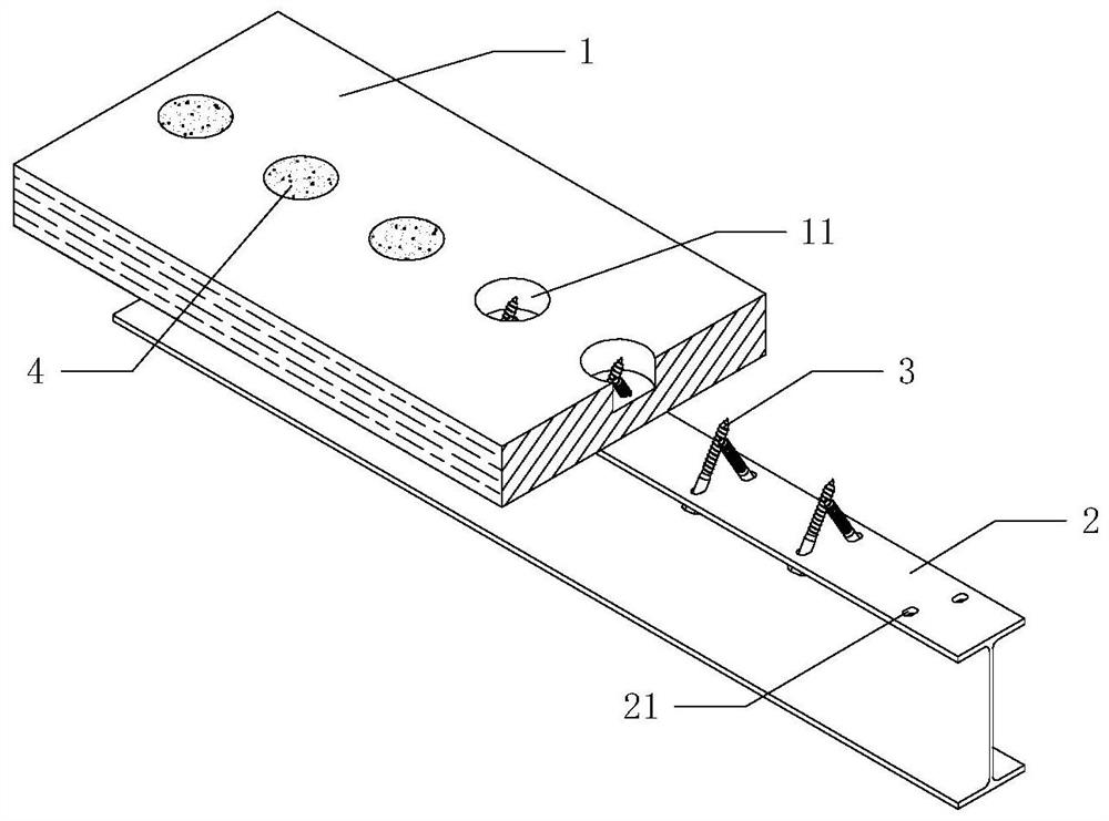
[0031] Such as image 3 , a cylindrical slot 11 is reserved on the upper surface of the plank 1, the depth of the slot 11 is 0.5 times the thickness of the plank 1, the steel member 2 is H-shaped steel, a long slot-shaped reserved hole 21 is reserved on the flange, and self-tapping screws 3 and the flange of the steel member 2 are screwed obliquely at a staggered angle, and are arranged symmetrically and staggered on both sides of the symmetry axis of the steel member 2 section. The tails of each two self-tapping screws 3 are located in the same reserved hole 21 of the wooden board 1, and After the self-tapping screw 3 was installed, pour mortar 4 into the slotted hole 11 of the plank 1 and smooth it out. Such as Figure 4 , the oblique side of the inclined washer 5 is closely attached to the inner surface of the flange of the steel member 2, and the other side is closely attached to the inner surface of the head of the self-tapping screw 3.

Embodiment 3

[0033] Such as Figure 5 , the upper surface of the plank 1 is reserved with a long groove-shaped slot 11, the depth of the slot 11 is 0.5 times the thickness of the plank 1, the steel member 2 is a rectangular tube with a welded flange, and a long groove-shaped reserved hole 21 is reserved on the flange , the self-tapping screws 3 are screwed in obliquely to the flange of the steel member 2, and are arranged symmetrically on both sides of the symmetry axis of the cross-section of the steel member 2. Mortar 4 and smooth.


PUM


Abstract

The invention discloses a steel-wood mixed connection structure, which comprises a wood board and a steel member. A slot hole is arranged on the side of the wood board different from the steel member. The depth of the slot hole is smaller than the thickness of the wood board. The tapping screw is anchored into the wood board through the reserved hole of the steel member, and the tail extends into the reserved slot hole of the wood board, and the slot hole is filled with mortar. The invention reserves a slot hole in the wood board, and the tail of the self-tapping screw extends into the reserved slot hole of the wood board, and pours mortar into it, which can play a kind of end anchoring effect on the screw, and improve the shear bearing capacity and rigidity of the screw connection. Prevent the screw from being pulled out due to excessive sliding deformation, and at the same time expand the stress area of ​​the wood at the tip of the screw to prevent splitting and local crushing.

Description

technical field [0001] The invention belongs to a connection structure, in particular to a steel-wood hybrid connection structure. Background technique [0002] Since the emergence of steel-concrete composite beams in the 1920s, traditional steel-concrete composite floors have been widely used in multi-story buildings. However, the heavy weight of concrete increases the total weight of the building by about 50%. Under the action of an earthquake, it causes a large lateral force, which is not conducive to the earthquake resistance of the structure. In addition, pouring concrete on site and maintaining it will greatly increase the construction time and cost, and will easily pollute the environment. As an environmentally friendly green renewable building material, wood has been widely focused. In the past two decades, more and more researches have focused on the application of wood in multi-story buildings, but the strength of pure wood structures is insufficient, and fire pro...

Claims


Application Information

Patent Timeline
Patent Type & Authority Patents(China)
IPC IPC(8): E04B1/30
CPCE04B1/30
Inventor 王春林吕佳峰赵京杨会峰
Owner SOUTHEAST UNIV
Why Eureka
Try Eureka