
Lifting appliance equipment for nuclear power shielding factory building and installation method

A technology for shielding workshops and installation methods, applied in the directions of transportation and packaging, load hanging components, cranes, etc., can solve the problem that the nuclear power site does not have a large-scale assembly site, etc. The effect of the number of uses

Inactive Publication Date: 2019-10-22
SHANDONG NUCLEAR POWER EQUIP MFG
View PDF6 Cites 1 Cited by
  • Summary
  • Abstract
  • Description
  • Claims
  • Application Information

AI Technical Summary

Problems solved by technology

[0006] In order to overcome the deficiencies of the prior art, the present invention provides a spreader device for a nuclear power shielding plant, which can facilitate the hoisting and positioning of each sub-module, correspondingly reduce the number of times and the cost of using a large-volume and large-tonnage crane, and solve the problem of nuclear power on-site The problem of having a large-area assembly site

Method used


Image

  • Lifting appliance equipment for nuclear power shielding factory building and installation method
  • Lifting appliance equipment for nuclear power shielding factory building and installation method
  • Lifting appliance equipment for nuclear power shielding factory building and installation method

Examples


Embodiment 1

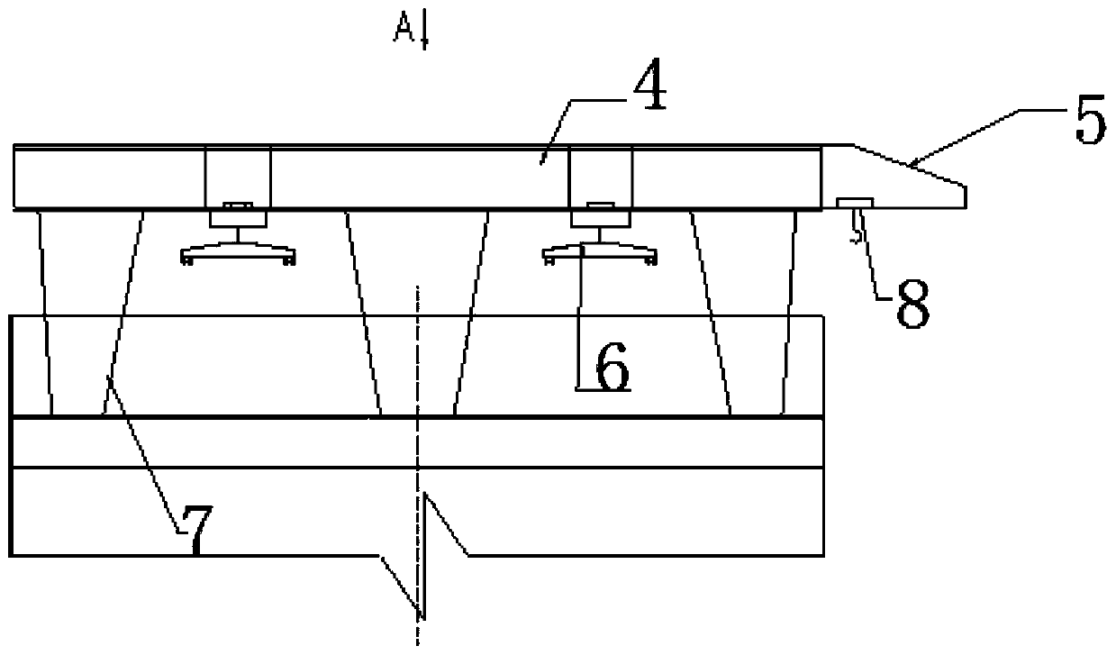
[0058] In a typical embodiment of the present invention, such as image 3 and Figure 4 As shown, the spreader equipment installed on the suspension beam of the steel containment ring is the first spreader, and the first spreader includes a ring-shaped first main structure 4, which is a truss structure, and the cross-section of the first main structure 4 It is rectangular, and the first main body structure 4 is supported by a plurality of legs. In this embodiment, the legs 7 are supported by steel containment ring suspension beams, and there are six legs 7, and the legs 7 are Trapezoidal truss structure, a 360° circular track 9 is provided on the outer side of the lower surface of the first main structure 4, and a number of rotary cantilevers 5 are arranged through the circular track 9, and the rotary cantilever 5 can run on the circular track 9 through the traveling mechanism and supporting wheels , The lower end surface of the rotary cantilever 5 is provided with an introdu...

Embodiment 2

[0066] The installation method of the shielded factory building includes the following contents:

[0067] 1) Installation of sub-modules below the steel containment cylinder elevation:

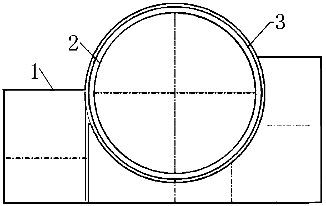
[0068] The shielding factory building is from 1 to 5 floors, and several assembled sub-modules on each floor ( Figure 7 The submodules numbered ①~⑥) are mainly within the range of 180°~360°, and are hoisted and installed by the first spreader, or according to the layered elevation position of the shielded workshop and the hoisting weight of the submodule, use a 30t~120t wheeled crane or Car cranes are hoisted and installed in place. According to the planning of the nuclear island hoisting area, the stations of cranes or truck cranes are distributed in the outer area of ​​the containment building, such as Figure 7 shown;

[0069] From the 6th floor to the 14th (m is greater than 2) floors, the sub-modules here are the whole ring structure, and the sub-modules distributed in the inner area o...


PUM


Abstract

The invention discloses lifting appliance equipment for a nuclear power shielding factory building and an installation method. The lifting appliance equipment for the nuclear power shielding factory building and the installation method solve the problems in the prior art that the integral lifting has relatively high requirements on lifting equipment and needs a large-area assembling site, and havethe beneficial effects of reducing the use of large-tonnage lifting equipment, and occupying less floor space. According to the technical scheme, the lifting appliance equipment for the nuclear powershielding factory building comprises a main structure, a rotary cantilever and an introduction trolley, wherein the main structure is supported by supporting legs and is provided with an annular or semi-annular track; the rotary cantilever is arranged on the track of the main structure through a travelling mechanism and is provided with an introduction track; and the introduction trolley can moverelative to the rotary cantilever, is supported by the introduction track and is connected to a lifting mechanism.

Description

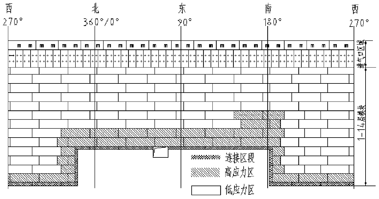
technical field [0001] The invention relates to the field of nuclear power welding, in particular to a spreader device and an installation method for a nuclear power shielding workshop. Background technique [0002] The shielding building of a nuclear power plant is one of the important structures for the nuclear power plant to resist internal and external accidents. It has main functions such as shielding radiation and flying object protection. The steel plate concrete structure adopted for the first time in the design is an integral part of the passive system of the shielding plant. It is called the shielding plant structure. The shell of the shielding plant structure of the CAP1400 nuclear power plant contains a total of about 163 sub-modules. Each sub-module is composed of inner and outer steel panels, such as figure 1 As shown, the back of the steel panel is welded with stiffeners, anchors and tension bars, with a maximum weight of about 26t. At present, the shielded f...

Claims


Application Information

Patent Timeline
Patent Type & Authority Applications(China)
IPC IPC(8): B66C23/68B66C23/62B66C13/08
CPCB66C13/08B66C23/62B66C23/68
Inventor 吴伟槐浩举王晓梅姜其岳朱恒雨宋瑛华张娜娜曹云廷刘振国
Owner SHANDONG NUCLEAR POWER EQUIP MFG
Learn More