
Multi-level reactive compensation system suitable for unbalanced load and control method of multi-level reactive compensation system

A technology for balancing loads and compensating systems, applied in reactive power compensation, reactive power adjustment/elimination/compensation, electrical components, etc., can solve problems such as reactive power, grid voltage fluctuations, grid line harmonics, etc., to achieve the total cost The effect of reducing, less harmonic content, and eliminating harmonics

Inactive Publication Date: 2019-10-18
HARBIN UNIV OF SCI & TECH
View PDF2 Cites 8 Cited by
  • Summary
  • Abstract
  • Description
  • Claims
  • Application Information

AI Technical Summary

Problems solved by technology

Especially with the rapid development of power electronics and its control technology, the grid-connected devices of power converters such as rectifiers and inverters have increased significantly. Influence, cause grid voltage fluctuations, bring a lot of harmonics and reactive power to the grid lines and other problems

Method used


Image

  • Multi-level reactive compensation system suitable for unbalanced load and control method of multi-level reactive compensation system
  • Multi-level reactive compensation system suitable for unbalanced load and control method of multi-level reactive compensation system
  • Multi-level reactive compensation system suitable for unbalanced load and control method of multi-level reactive compensation system

Examples


Embodiment Construction

[0042] Embodiments of the present invention are described below through specific examples, and those skilled in the art can easily understand other advantages and effects of the present invention from the content disclosed in this specification. The present invention can also be implemented or applied through other different specific implementation modes, and various modifications or changes can be made to the details in this specification based on different viewpoints and applications without departing from the spirit of the present invention. It should be noted that, in the case of no conflict, the following embodiments and features in the embodiments can be combined with each other.

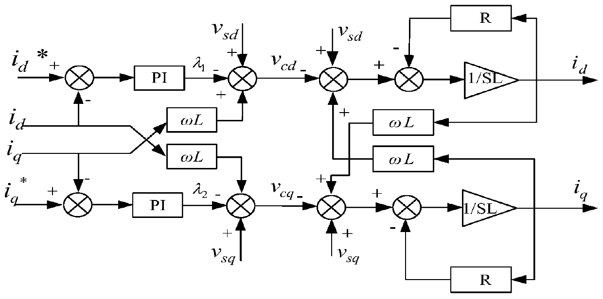
[0043] Such as figure 1 As shown, a multi-level reactive power compensation system suitable for unbalanced loads includes a controller, a sampling unit, a current sampling and conditioning circuit, a drive circuit, a protection circuit and a compensation device. The compensation device include...


PUM


Abstract

The invention relates to a multi-level reactive compensation system suitable for an unbalanced load and a control method of the multi-level reactive compensation system and belongs to the field of thereactive compensation of electric power systems. According to the multi-level reactive compensation system, a convection circuit includes a direct current link and an inversion circuit which are connected in parallel; the direct current link comprises a plurality of direct current link circuit units which are connected in series; each direct current link unit comprises a switching tube S1, a switching tube S2 and a capacitor C1; the positive pole of the capacitor C1 is connected with the collector of the switching tube S1; the emitter of the switching tube S1 is connected with the collector of the switching tube S2; and the emitter of the switching tube S2 is connected with the negative pole of the capacitor C1. The number of switches and the number of grid drivers can be remarkably reduced compared with a cascade H-bridge structure, therefore, the system is easier to expand, and can effectively inhibit and eliminate harmonic waves in a reactive current compensation process.

Description

technical field [0001] The invention relates to the field of reactive power compensation in electric power systems, in particular to a multi-level reactive power compensation system suitable for unbalanced loads and a control method thereof. Background technique [0002] As one of the most important energy sources in the world today, electric energy provides power for industrial automation production and is closely related to people's daily life. It has become an important part of a civilized society. At the same time, it also reflects a country's economic development and comprehensive national strength. With the rapid development of my country's economy and the continuous improvement of industrial automation, the complexity of the power grid has greatly increased. Therefore, it is necessary to consider various issues to ensure the stable operation of the power grid. Especially with the rapid development of power electronics and its control technology, the grid-connected dev...

Claims


Application Information

Patent Timeline
Patent Type & Authority Applications(China)
IPC IPC(8): H02J3/18H02J3/01H02J3/26H02J3/16H02M7/483
CPCH02J3/01H02J3/16H02J3/1821H02J3/26H02M7/483H02M1/0012Y02E40/30Y02E40/40Y02E40/50
Inventor 高晗璎程喆
Owner HARBIN UNIV OF SCI & TECH
Learn More