Plug-in connector for differential data transmission

A plug-in connector and differential data technology, which is applied in the direction of connection, two-part connection device, and parts of the connection device, can solve the problems that cannot be applied to products with small external dimensions, cannot meet the processing requirements of parts, and have harsh processing technology, etc. problems, to achieve the effect of eliminating short stub effect, improving signal quality, and improving signal crosstalk

Active Publication Date: 2019-10-18
CHINA AVIATION OPTICAL-ELECTRICAL TECH CO LTD
View PDF4 Cites 0 Cited by
  • Summary
  • Abstract
  • Description
  • Claims
  • Application Information

AI Technical Summary

Problems solved by technology

With the development of miniaturization of this type of connector products, this structure cannot be applied to products with smaller dimensions, mainly because the cross-shielding structural parts are more demanding on processing technology, and due to the limitation of volume and minimum wall thickness, it cannot be made smaller ; If the part wall of the cross shielding structure is too thin, it will not only fail to meet the processing requirements of the part, but also be easily damaged during the insertion process

Method used


Image

  • Plug-in connector for differential data transmission
  • Plug-in connector for differential data transmission
  • Plug-in connector for differential data transmission

Examples


Embodiment Construction

[0026] The technical solutions of the present invention will be further described in detail below in conjunction with the accompanying drawings and preferred embodiments.

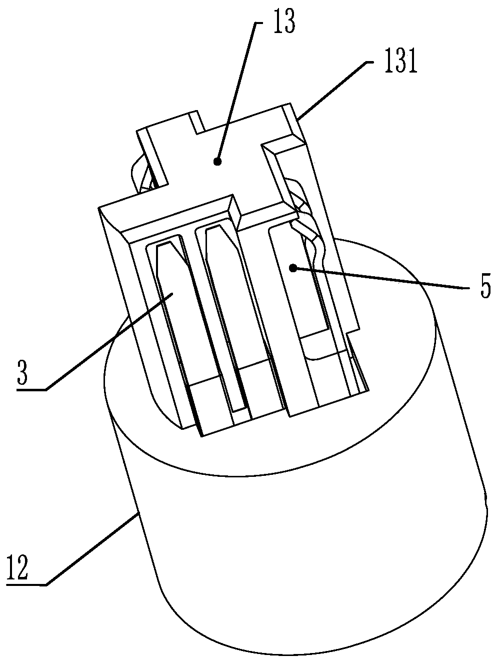
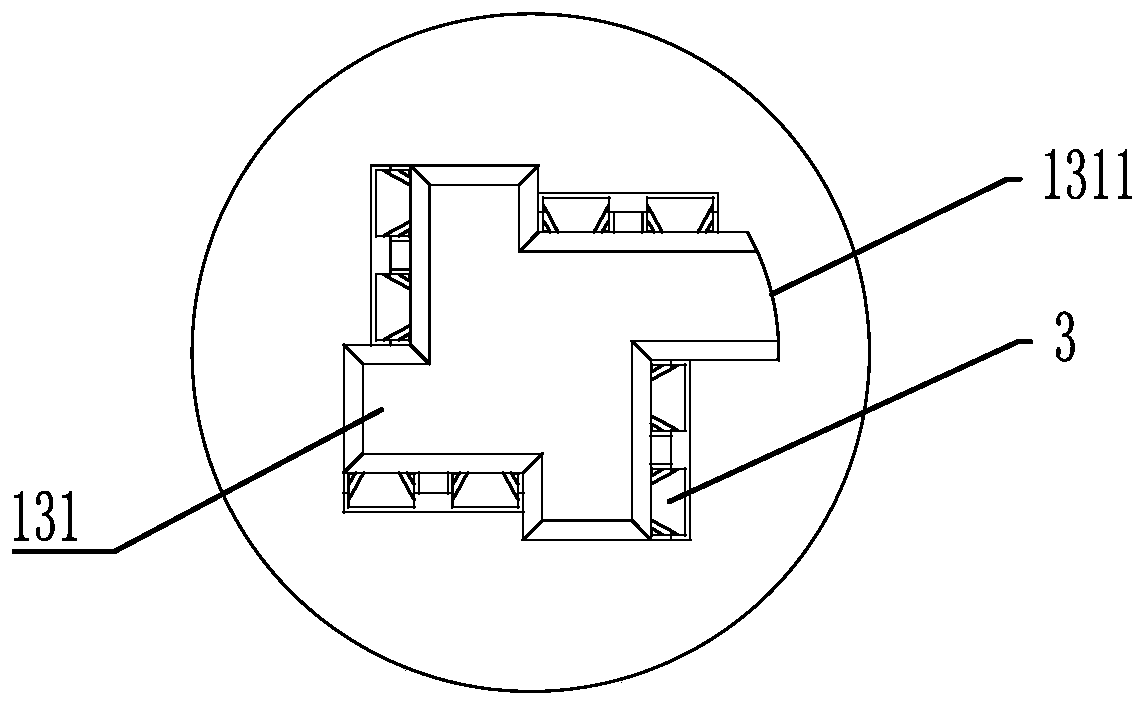
[0027] A specific embodiment of a plug connector for differential data transmission proposed by the present invention: as Figure 2 to Figure 7 As shown, it includes a plug connector and a socket connector for matching use. The plug connector includes a plug tail sleeve 12 installed in the plug housing 11 and a plug tail sleeve 12 installed in the plug tail sleeve 12 and protruding from the top of the plug tail sleeve. The plug insulator 13, the plug insulator 13 has four axially arranged protrusions 131 along the circumferential direction, so that the entire plug insulator is similar to a windmill shape, the circumferentially adjacent protrusions are perpendicular to each other, and the same side of each protrusion 131 is provided with parallel The plug blade contacts 3 are arranged, and the plug blade con...


PUM


Abstract

The invention discloses a plug-in connector for differential data transmission. The plug-in connector comprises a plug connector and a socket connector; the plug connector comprises a plug tail sleeveand a plug insulator; the plug tail sleeve is mounted in a plug shell; the plug insulator is mounted in the plug tail sleeve; the plug insulator is provided with a plurality of axially-arranged protrusions in the circumferential direction; the same side of each protrusion is provided with plug sheet type contact pieces arranged in parallel; the plug sheet type contact pieces located on the side parts of the adjacent protrusions are perpendicular mutually; the socket connector comprises a socket tail sleeve mounted in a socket shell and a socket insulator mounted in the socket tail sleeve; a cavity matched with the plug insulator in an inserted mode is formed in the socket insulator; and the cavity is internally provided with socket sheet type contact pieces which correspond to the plug sheet type contact pieces and are matched with the plug sheet type contact pieces in a mutual pushing mode to realize electrical connection. According to the plug-in connector, through reasonable spatial distribution of the contact pieces, the product miniaturization development trend can be adapted, and the short pile effect and the signal crosstalk during high-frequency signal transmission can beeffectively eliminated.

Description

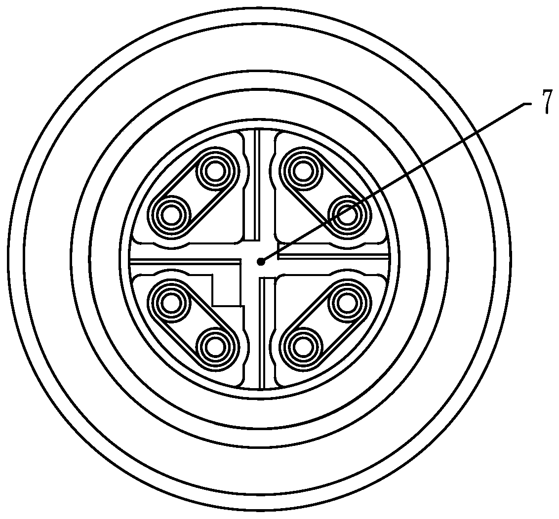
technical field [0001] The invention belongs to the field of differential connectors, in particular to a plug connector for differential data transmission. Background technique [0002] Differential connectors are mainly used for high-speed data signal transmission, the existing M12 differential connectors such as figure 1 As shown, the cross shield structure 7 is used to divide the eight round pin / round hole contacts into four differential pairs, and the cross shield structure is connected to the shell shield to play a shielding role to achieve high-speed performance transmission. With the development of miniaturization of this type of connector products, this structure cannot be applied to products with smaller dimensions, mainly because the cross-shielding structural parts are more demanding on processing technology, and due to the limitation of volume and minimum wall thickness, it cannot be made smaller ; If the part wall of the cross shielding structure is too thin, i...

Claims


Application Information

Patent Timeline
Patent Type & Authority Applications(China)
IPC IPC(8): H01R13/26H01R13/646H01R13/6461H01R13/502H01R13/631H01R13/40H01R13/405H01R24/00
CPCH01R13/26H01R13/40H01R13/405H01R13/502H01R13/631H01R13/646H01R13/6461H01R24/00
Inventor 王新刘毓王瑞婷崔艳磊张志中
Owner CHINA AVIATION OPTICAL-ELECTRICAL TECH CO LTD
Why Eureka
Try Eureka