
Antenna and electronic device

一种电子设备、天线的技术,应用在通讯领域,能够解决天线高、不符合天线小型化等问题,达到体积小、结构简单、降低天线剖面的效果

Active Publication Date: 2019-10-18
AAC TECH NANJING
View PDF6 Cites 9 Cited by
  • Summary
  • Abstract
  • Description
  • Claims
  • Application Information

AI Technical Summary

Problems solved by technology

However, the existing antenna profile is relatively high, which does not meet the requirements of antenna miniaturization

Method used


Image

  • Antenna and electronic device
  • Antenna and electronic device
  • Antenna and electronic device

Examples


Embodiment Construction

[0028] In order to make the object, technical solution and advantages of the present invention clearer, the present invention will be further described in detail below in conjunction with the accompanying drawings and embodiments. It should be understood that the specific embodiments described here are only used to explain the present invention, not to limit the present invention. Based on the embodiments of the present invention, all other embodiments obtained by persons of ordinary skill in the art without making creative efforts belong to the protection scope of the present invention.

[0029] The terms "first", "second", "third", "fourth", etc. (if any) in the description and claims of the present invention and the above drawings are used to distinguish similar objects, and not necessarily Used to describe a specific sequence or sequence. It is to be understood that the terms so used are interchangeable under appropriate circumstances such that the embodiments described h...


PUM


Abstract

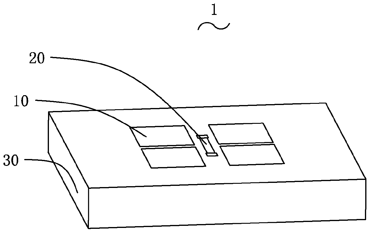
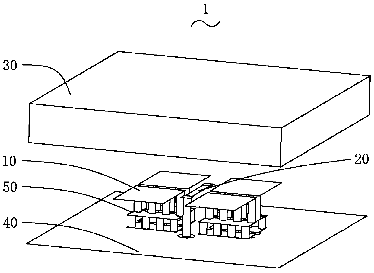
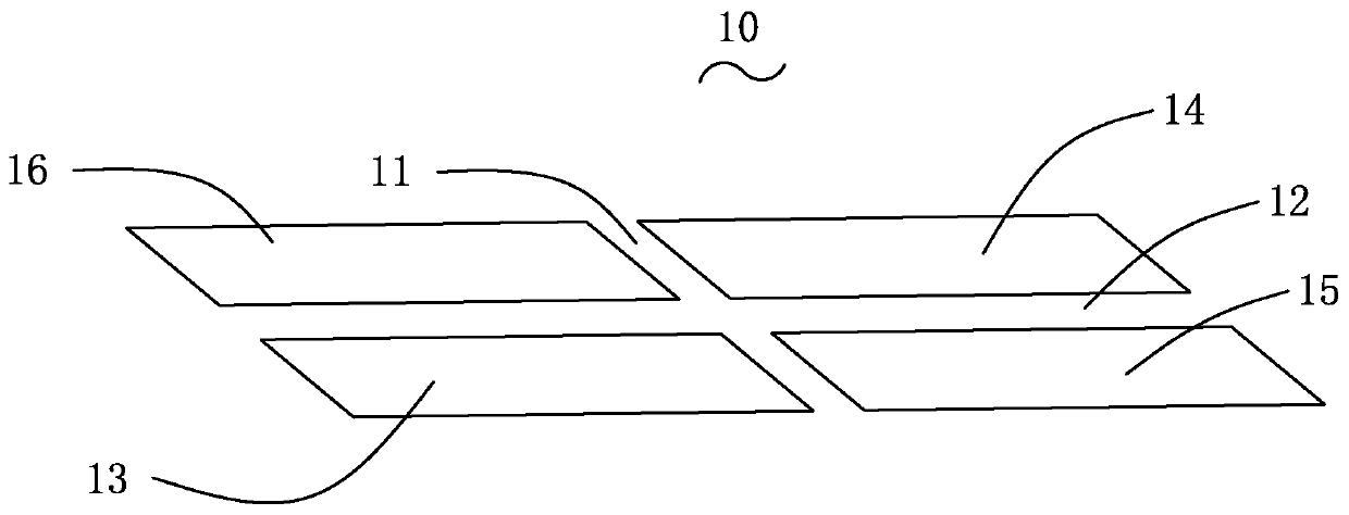
The invention relates to an antenna and an electronic device. The antenna includes a radiating portion, a grounding piece spaced apart from the radiating portion and multiple grounding connecting portions electrically connecting the radiating portion and the grounding piece, wherein the radiating portion includes four radiators distributed in a 2*2 plane array, the radiators are spaced apart fromeach other to form first and second gaps which are perpendicular to each other at the center of the plane array, each radiator is electrically connected with the grounding piece through one groundingconnecting portion, the grounding connecting portion includes at least one patch and multiple metal through holes, the patch and the metal through holes are located between the plane array and the grounding piece, the at least one patch and the radiators are located on different planes and are parallel to each other, each side of two opposite sides of each patch is at least electrically connectedwith one metal through hole, and each side of the patch is electrically connected with the adjacent radiator, the patch or the grounding piece through the at least one metal through hole. The electronic device includes the antenna. The antenna is advantaged in that the antenna has low profile.

Description

【Technical field】 [0001] The invention relates to the technical field of communication, in particular to an antenna and electronic equipment. 【Background technique】 [0002] The fifth-generation mobile communication technology will greatly change people's existing lifestyle and promote the continuous development of society. Electromagnetic dipole antenna is a directional complementary antenna structure, which is a combination of electric dipole and magnetic dipole antenna. It has a wide working bandwidth and good directivity in the working frequency band, so it is widely used In the base station antenna of the mobile communication system. However, the existing antenna has a relatively high profile, which does not meet the requirement for miniaturization of the antenna. [0003] Therefore, it is necessary to provide a solution with a low antenna profile to solve the above problems. 【Content of invention】 [0004] The object of the present invention is to provide an anten...

Claims


Application Information

Patent Timeline
Patent Type & Authority Applications(China)
IPC IPC(8): H01Q1/38H01Q1/48H01Q1/50H01Q21/06H01Q21/00
CPCH01Q1/38H01Q1/48H01Q1/50H01Q21/065H01Q21/0006H01Q21/061H01Q21/0075H01Q21/0081
Inventor 陈思武景
Owner AAC TECH NANJING
Learn More