Gas detecting device with adjustable light path

A technology of gas detection and optical path, which is applied in measuring devices, color/spectral characteristic measurement, material analysis through optical means, etc. It can solve the problem of relatively high professional technical level of operators, sealing gasket 22 cannot be reused, and personnel training Problems such as high investment cost, to achieve the effect of small training input cost, low professional technical level, and high adjustment efficiency

Pending Publication Date: 2019-10-18
内蒙古光能科技有限公司
View PDF0 Cites 1 Cited by
  • Summary
  • Abstract
  • Description
  • Claims
  • Application Information

AI Technical Summary

Problems solved by technology

[0003] The existing measuring device has the following problems during use: 1. When the optical path is changed by rotating the high-reflection mirror 5, the gland 21, the sealing gasket 22 and the pressure ring 7 need to be removed. After the position adjustment of the high-reflection mirror 5 is completed Install the pressure ring 7, the sealing gasket 22 and the gland 21 again. Once it is found that the optical path is not adjusted to the optimum position, the gland 21, the sealing gasket 22 and the pressure ring 7 need to be disassembled again to adjust the high reflective lens 5. The adjustment process is cumbersome and the adjustment efficiency is low; 2. The light pipe 1 and the adjustment seat plate 15 are respectively fixed on the bracket independently. The position of the optical path is adjusted by adjusting the seat plate 15 in the horizontal direction. The adjustment process is cumbersome, and the professional technical level of the operators is relatively high, and the investment cost of personnel training is large; It is about 800 yuan, and the cost is relatively high. If the observation window glass 6 is damaged, the gland 21 needs to be replaced as a whole, and the maintenance cost is high; On the sealing gasket 22, the sealing of the air chamber is realized, and the sealing gasket 22 will be damaged by the sealing blade. When the high reflection lens 5 is adjusted, when the gland 21 is reinstalled, a new sealing gasket 22 needs to be replaced to ensure The tightness of the air chamber, the sealing gasket 22 cannot be reused, and the investment cost is high

Method used


Image

  • Gas detecting device with adjustable light path
  • Gas detecting device with adjustable light path
  • Gas detecting device with adjustable light path

Examples


Embodiment Construction

[0023] The following will clearly and completely describe the technical solutions in the embodiments of the present invention with reference to the accompanying drawings in the embodiments of the present invention. Obviously, the described embodiments are only some, not all, embodiments of the present invention. Based on the embodiments of the present invention, all other embodiments obtained by persons of ordinary skill in the art without making creative efforts belong to the protection scope of the present invention.

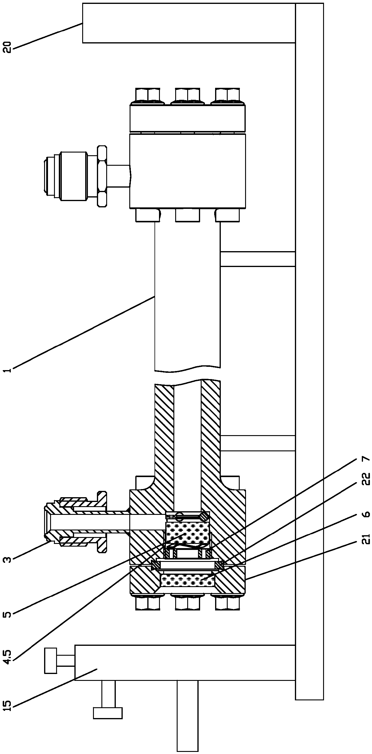
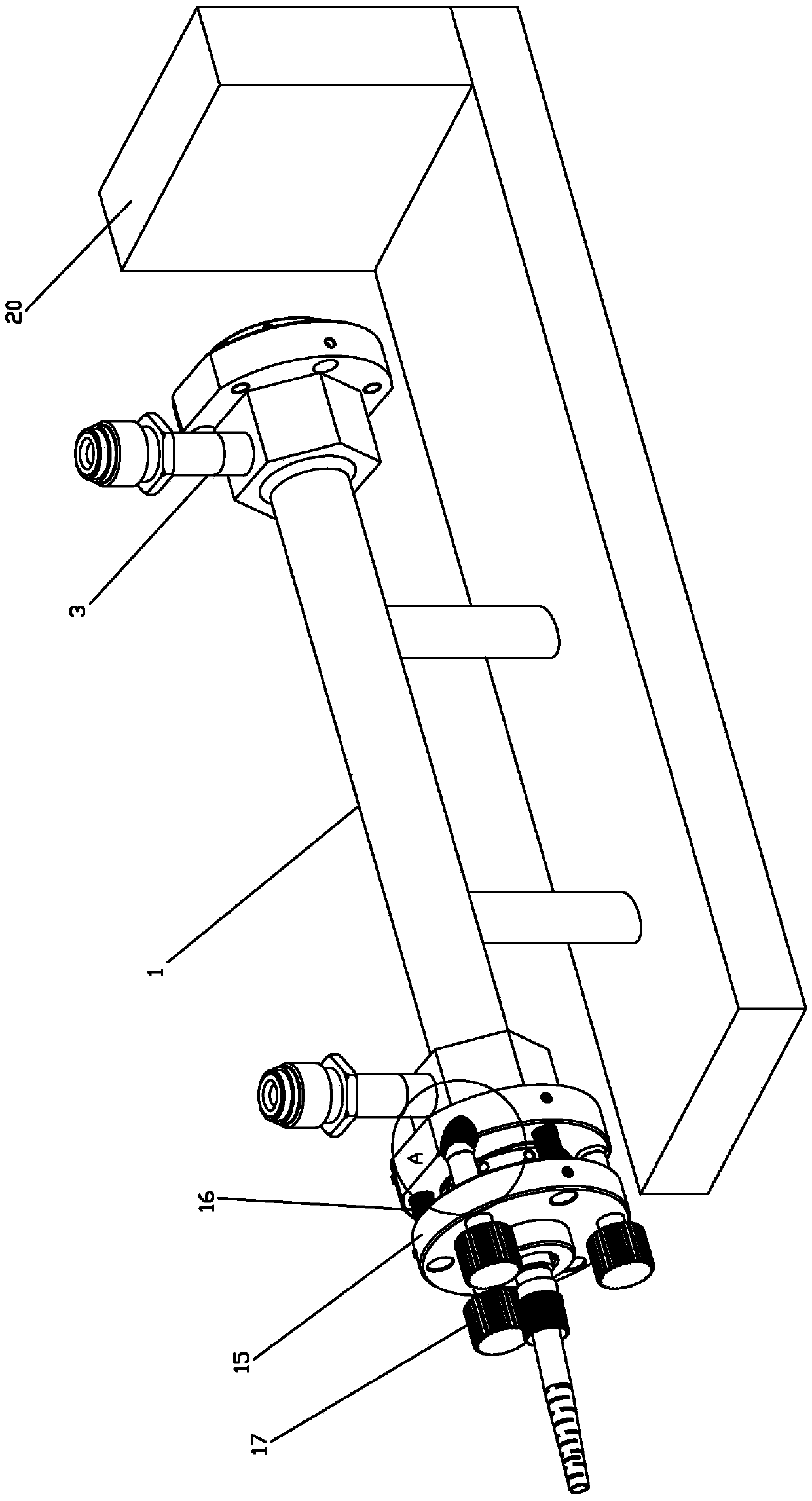
[0024] Such as Figure 2-6 As shown, a gas detection device with an adjustable optical path includes a light pipe 1, and a lens group module 2 is arranged on the gas chamber opening at both ends of the light pipe 1, and a lens group module 2 is arranged on the side wall of the light pipe 1. There are two gas line connecting pipes 3 communicating with the gas chamber 1.1, which are used to pass the gas to be measured into the gas chamber 1.1.

[0025] The lens...


PUM


Abstract

The invention discloses a gas detecting device with the adjustable light path. The gas detecting device comprises a light pipe. Mirror group modules are plugged to gas chamber outlets at the two endsof the light pipe separately and movably in a split manner. Two gas path connecting pipes communicated with a gas chamber are arranged at the side wall of the light pipe. The mirror group modules include mirror group connectors, high reflection lenses, observation window lenses, and pressing rings. The gas detecting device has the following advantages: the mirror group modules are screwed to the ogas chamber outlets at the two ends of the light pipe; when the high reflection lenses need to be rotated to change light paths, the mirror group modules are rotated directly without dismounting theobservation window lenses, so that the operation becomes simple and the adjustment efficiency is high; the light pipe and an adjusting seat plate are connected by a tension spring and a fine adjustment screw and thus the position of the light path is limited in vertical and horizontal directions, so that the operation of adjusting the position of the light path in vertical and horizontal directions is avoided in the need of light path direction adjustment, so that the adjusting step is removed and thus the professional skill level requirement of the operator is reduced and the personnel training input cost is low.

Description

Technical field: [0001] The invention relates to the technical field of gas analysis, in particular to a gas detection device with adjustable optical path. Background technique: [0002] When using the principle of optical cavity ring-down to measure the composition of trace gases, the most common measuring devices such as figure 1 As shown, the light pipe 1 and the adjusting seat plate 15 are independently fixed on the brackets, the gas enters the light pipe 1 through the gas pipe connection 3, and the laser travels back and forth between the high reflection mirrors 5 at both ends of the light pipe 1, and is measured by the detector 20 Cavity Ring-Down Spectroscopy. The high-reflection lens 5 is split and plugged in the high-reflection lens cavity 4.5 at both ends of the light pipe 1, and a pressure ring 7 is screwed in the mouth of the high-reflection lens cavity 4.5, and the pressure ring 7 limits the high-reflection lens 5 to a high reflection Inside the lens cavity 4....

Claims


Application Information

Patent Timeline
Patent Type & Authority Applications(China)
IPC IPC(8): G01N21/01G01N21/25
CPCG01N21/01G01N21/25G01N2021/0112
Inventor 李洁阎文斌呼良俊
Owner 内蒙古光能科技有限公司
Why Eureka
Try Eureka