


Quick Research
Generate reliable direction feasibility study reports for your R&D in just a few steps.

Technical Q&A
Discover and master advanced knowledge NOW. Basics, ideas, possibilities, all at once.

Find Solutions
As an expert in R&D theories, this can generate solutions to your technical problems instantly.

Evaluate Feasibility
Analyze your overall solution with one click, know your potential R&D risks in advance.

Monitor Landscape
Get weekly tech updates, stay abreast of the latest tech innovations and key insights.
An anti-seismic building steel structure
A technology of steel structure and building steel, applied in the direction of building components, buildings, building types, etc., can solve problems such as general seismic effect
- Summary
- Abstract
- Description
- Claims
- Application Information
AI Technical Summary
Problems solved by technology
Method used
Image

Examples
specific Embodiment approach 1
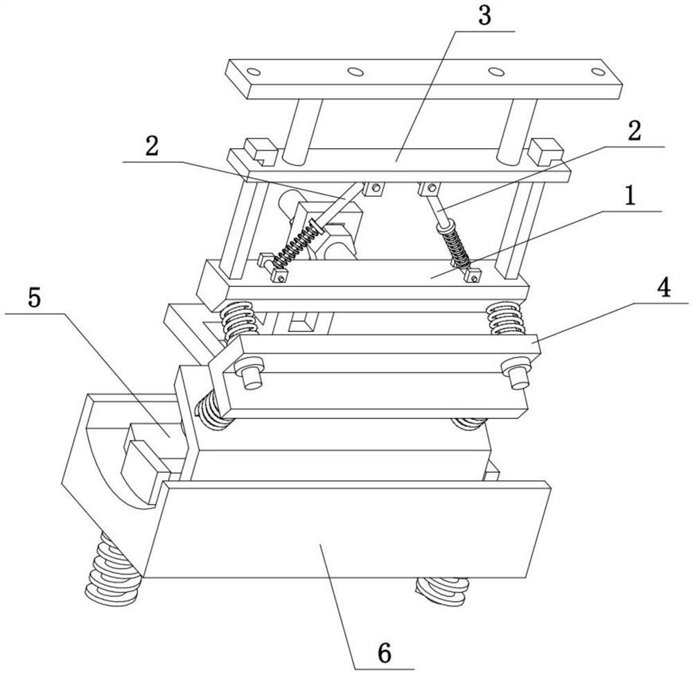
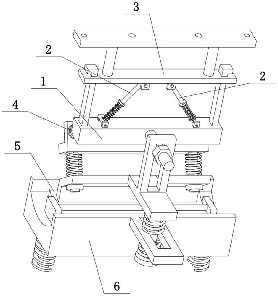
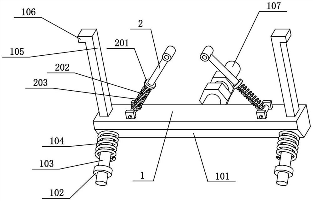
[0033] Combine below Figure 1-10 Describe this embodiment, the present invention relates to the field of construction, more specifically, an earthquake-resistant building steel structure, including a horizontal steel bar 1, a lower slope 101, a spring sleeve I103, a spring I104, a vertical rail rod 105, a hollow rod 2, The circular ring 201, the plunger 202, the spring II203, the up and down moving plate 3 and the inclined plate I4, the present invention can be multi-stage anti-seismic, effectively anti-seismic to the vibration that the steel structure is subjected to.
[0034]The lower side of the horizontal steel bar 1 is provided with a lower inclined surface 101, and the left and right ends of the lower inclined surface 101 are fixedly connected with spring sleeves I103, and the two spring sleeves I103 are sleeved with springs I104. The left and right ends are respectively slidably connected to two spring sleeves I103, and the two springs I104 are located between the hori...
specific Embodiment approach 2
[0036] Combine below Figure 1-10 To illustrate this embodiment, the earthquake-resistant building steel structure also includes a retaining ring I102 and a retaining block 106, the upper ends of the two vertical rails 105 are fixedly connected to the retaining block 106, and the lower ends of the two spring sleeve columns I103 are fixedly connected to the retaining block. The ring I102, the two retaining rings I102 are all located on the lower side of the inclined plate I4. The effect of two retaining rings I102 is to prevent two spring sleeve posts I103 from breaking away from the inclined plate I4, and the effect of two stoppers 106 is to prevent that moving plate 3 up and down breaks away from two vertical rail bars 105.
specific Embodiment approach 3
[0038] Combine below Figure 1-10 To illustrate this embodiment, the earthquake-resistant building steel structure also includes a connecting column 301 and a top bar 302, the left and right ends of the up and down moving plate 3 are fixedly connected with the connecting column 301, and the upper ends of the two connecting columns 301 are fixedly connected with a top bar. The bar 302 and the top bar 302 are provided with a plurality of threaded holes. A plurality of threaded holes are provided on the top bar 302 to insert screws, thereby facilitating the installation of the roof of the building.
PUM
 Abstract
Description
Claims
Application Information
 - R&D Engineer
- R&D Manager
- IP Professional
- Industry Leading Data Capabilities
- Powerful AI technology
- Patent DNA Extraction
Browse by: Latest US Patents, China's latest patents, Technical Efficacy Thesaurus, Application Domain, Technology Topic, Popular Technical Reports.
© 2024 PatSnap. All rights reserved.Legal|Privacy policy|Modern Slavery Act Transparency Statement|Sitemap|About US| Contact US: help@patsnap.com