Local laminated slab connection joint and construction method thereof

A technology for connecting nodes and construction methods, which is applied to floors, building components, buildings, etc., can solve the problems of rising construction costs, slow construction speed, cracking of floors, etc., and achieve the effect of improving stiffness and bearing capacity

Active Publication Date: 2019-10-18
ZHEJIANG DADONGWU CONSTR TECH CO LTD
View PDF7 Cites 3 Cited by
  • Summary
  • Abstract
  • Description
  • Claims
  • Application Information

AI Technical Summary

Problems solved by technology

Such a design not only increases the amount of steel used, but also tends to crack the floor during the use stage, affecting the use of users.
If the two-way stressed laminated slabs are jointed by post-casting belts, formwork construction is required, and temporary leveling measures are used under the laminated slabs under the action of top bracing and beams; resulting in slow construction speed and increased construction costs

Method used


Image

  • Local laminated slab connection joint and construction method thereof
  • Local laminated slab connection joint and construction method thereof
  • Local laminated slab connection joint and construction method thereof

Examples


Embodiment Construction

[0025] The present invention will be further described below in conjunction with the embodiments in the accompanying drawings.

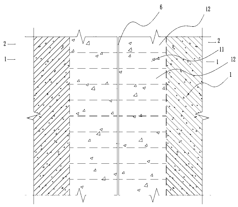
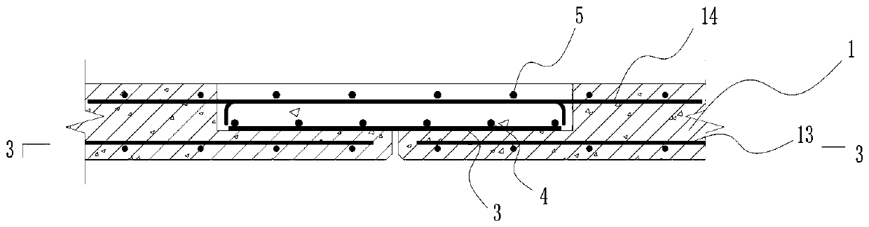
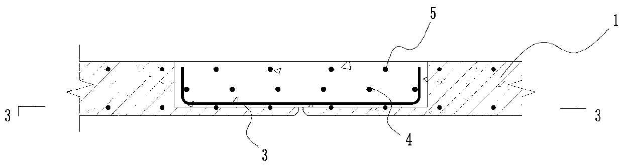
[0026] Such as Figure 1 to Figure 5 The partial laminated slab connection node shown includes two prefabricated slabs 1, a groove 11 is provided at the end of the prefabricated slab 1, and a bottom groove 12 is provided in the groove 11, and the bottom grooves 12 on the two prefabricated slabs 1 are opposite to each other. Set and form a through groove, the bottom groove 12 is provided with the first reinforcement 2, the groove 11 is provided with the second reinforcement 3, and the upper side of the second reinforcement 3 is provided with a third reinforcement perpendicular to the second reinforcement 3. Rib 4, the prefabricated panel 1 is provided with a top reinforcement 14, the top reinforcement 14 extends from the side wall of the groove 11 to the upper end of the groove 11 relative to the prefabricated panel 1, and the top reinforcement 14 is ...


PUM

PropertyMeasurementUnit
Lengthaaaaaaaaaa
Depthaaaaaaaaaa
Depthaaaaaaaaaa

Abstract

The invention provides a local laminated slab connection joint. The connection joint includes two prefabricated plates. The end parts of the prefabricated plates are provided with grooves. Bottom grooves are arranged in the grooves. The bottom grooves in the two prefabricated plates are arranged opposite to each other and form a through groove. First reinforcing ribs are arranged in the bottom grooves. Second reinforcing ribs are arranged in the grooves. The upper sides of the second reinforcing ribs are provided with third reinforcing ribs perpendicular to the second reinforcing ribs. The prefabricated plates are provided with top steel bars. The top steel bars extend from the side walls of the grooves to the upper ends of the grooves of the corresponding prefabricated plates. The upper sides of the top steel bars are provided with fourth reinforcing ribs. The local laminated slab connection joint can meet force transmission requirements of a two-way slab, and the rigidity and the bearing capacity of a connecting part are large.

Description

technical field [0001] The invention relates to the field of building technology, in particular to a connection node of a partially laminated plate and a construction method thereof. Background technique [0002] Concrete composite slab is a slab structure that combines prefabricated concrete slab and cast-in-place floor, which has the advantages of fast construction and saving formwork. The side splicing of one-way laminated slabs should adopt close splicing joints with additional steel bars, while the side splicing of two-way laminated slabs should adopt post-cast tape joints. Most of the floor slabs of residential buildings are two-way force-bearing slabs, and the traditional laminated slab structure cannot realize the two-way force-bearing function of laminated slabs. If the two-way stressed laminated slab is designed as a one-way slab, due to the stiffness of the post-casting layer, the floor slab still transmits force as a two-way slab first; after the joint position ...

Claims


Application Information

Patent Timeline
IPC IPC(8): E04B5/17
CPCE04B5/17
Inventor 娄峰陈忠覃祚威柳跃强
Owner ZHEJIANG DADONGWU CONSTR TECH CO LTD
Why Eureka
Try Eureka