
A cable pay-off coil device for civil engineering

A technology for civil engineering and pay-off reels, which is applied in the directions of transportation and packaging, thin material handling, and conveying filamentous materials. Effect

Active Publication Date: 2020-11-03
河南友鹏建设工程有限公司
View PDF11 Cites 0 Cited by
  • Summary
  • Abstract
  • Description
  • Claims
  • Application Information

AI Technical Summary

Problems solved by technology

At present, the diameter of the runner is mostly fixed, which is only suitable for placing wire coils of a fixed size. If the inner diameter of the wire coil is too small, the wire coil will shake, and the shaking effect of the wire coil when pulling the wire is easy to put pull down
In addition, the current pay-off device only has the function of laying and paying off the wire, and has no tensioning function. When the wire needs to be tensioned, it is necessary to hold the wire to perform the tensioning operation, which is inconvenient to operate.

Method used


Image

  • A cable pay-off coil device for civil engineering
  • A cable pay-off coil device for civil engineering
  • A cable pay-off coil device for civil engineering

Examples


Embodiment Construction

[0019] The present invention will be further described below in conjunction with the accompanying drawings and specific embodiments.

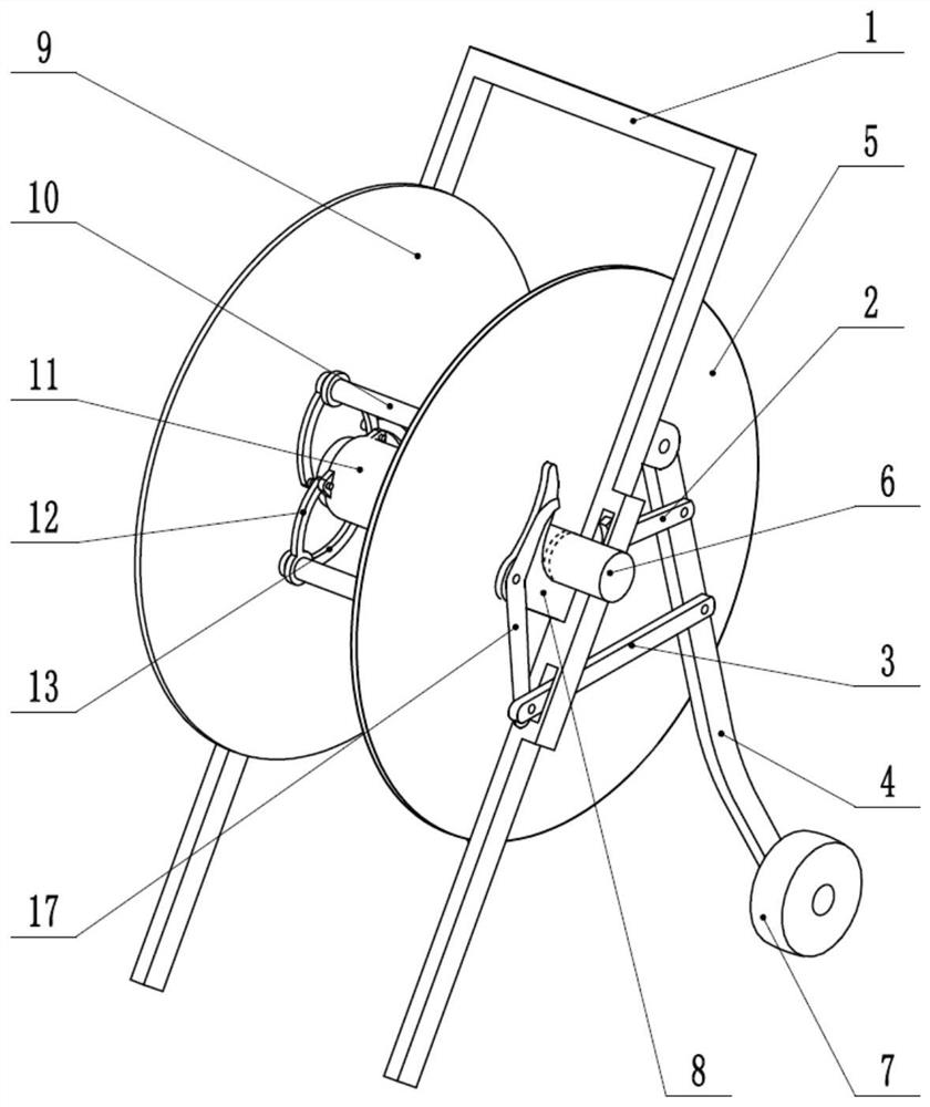
[0020] Such as Figures 1 to 8 As shown, the present invention includes a support base 1 and a runner.

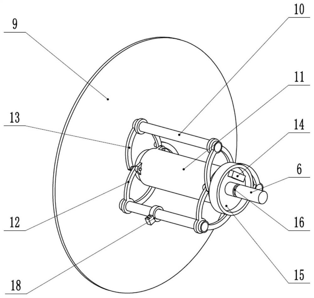
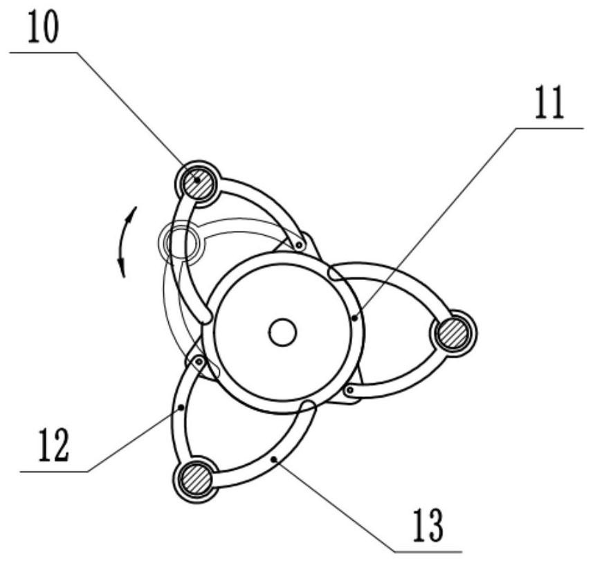
[0021] Such as figure 2 As shown, the runner includes a main shaft 6, a side plate, a cylindrical body 11, a cross bar 10, a connecting rod, a wire end holder 18 and a disc 15. The cylinder 11 is sleeved on the main shaft 6 and can rotate around the main shaft 6. There are two side plates, which are respectively located on both sides of the cylinder 11, one of which is a fixed side plate 9, fixed on On the main shaft 6, the other side plate is the movable side plate 5, which can be disassembled. On the main shaft 6, the position outside the movable side plate 5 is provided with an annular groove 16. After the movable side plate 5 is installed, a jump ring is installed in the annular groove 16. The movable side plate 5 can be fixed by the...


PUM


Abstract

The invention discloses a cable paying-off coiling device for civil engineering, and belongs to the field of wire laying tools. The cable paying-off coiling device is characterized in comprising a supporting base and a rotating wheel, wherein the rotating wheel comprises a main shaft, side plates, a cylinder body, cross rods, a connecting rod, a wire head fixer and a round plate; the two side plates are correspondingly positioned on the two sides of the cylinder body, the plurality of cross rods are distributed at the periphery of the main shaft in parallel, and the two ends of the cross rod are correspondingly provided with a first connecting rod and a second connecting rod; and a series of teeth are arranged at the end part, close to one end of the round plate, of the cylinder body, a clamping block is arranged on the round plate, a supporting base main body is of an n-shaped structure, supporting rods are hinged to each of the two sides of the n-shaped structure, two L-shaped partsare arranged on the two sides of the supporting base, and brake devices are arranged on the L-shaped parts on the supporting base. Compared with the prior art, the cable paying-off coiling device canadapt to wire coils of different specifications and can carry out wire tensioning operation.

Description

technical field [0001] The invention relates to a power laying tool, in particular to a cable pay-off coil device for civil engineering. Background technique [0002] During civil engineering construction, wire laying work is often required. In civil engineering construction, the distance of wire laying is often relatively long, so it is often necessary to use a pay-off device for laying, and the coiled wires are placed on the runners to facilitate pulling out the wires. At present, the diameter of the runner is mostly fixed, which is only suitable for placing wire coils of fixed size. If the inner diameter of the wire coil is too small, the wire coil will shake, and the shaking effect of the wire coil when pulling the wire is easy to put Pull down the threader. In addition, the current pay-off device only has the function of laying and unwinding the wires, and has no tensioning function. When the wires need to be tensioned, it is necessary to hold the wires for the tension...

Claims


Application Information

Patent Timeline
Patent Type & Authority Patents(China)
IPC IPC(8): B65H67/02B65H49/30B65H49/38B65H59/04
CPCB65H49/30B65H49/38B65H59/04B65H67/02B65H2701/34
Inventor 周栋卜亚楠蔡海勇
Owner 河南友鹏建设工程有限公司
Learn More