Mechanical bionic hand and thumb module thereof
A thumb and bionic hand technology, applied in the field of medical rehabilitation, can solve the problems of slow and insensitive movement, poor user experience and limited service life of flexible mechanisms, etc.
- Summary
- Abstract
- Description
- Claims
- Application Information
AI Technical Summary
Problems solved by technology
Method used
Image

Examples
Embodiment 1
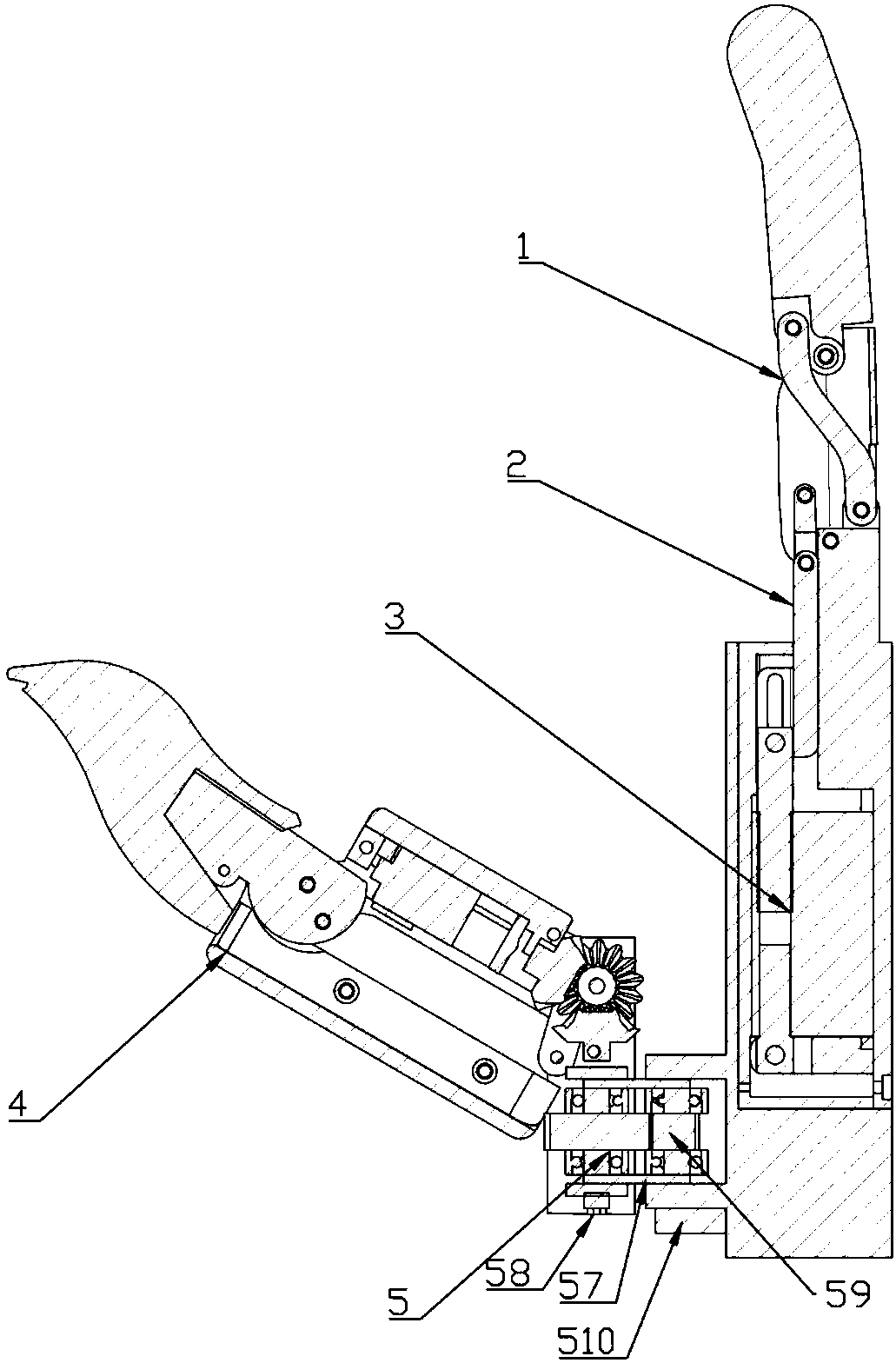
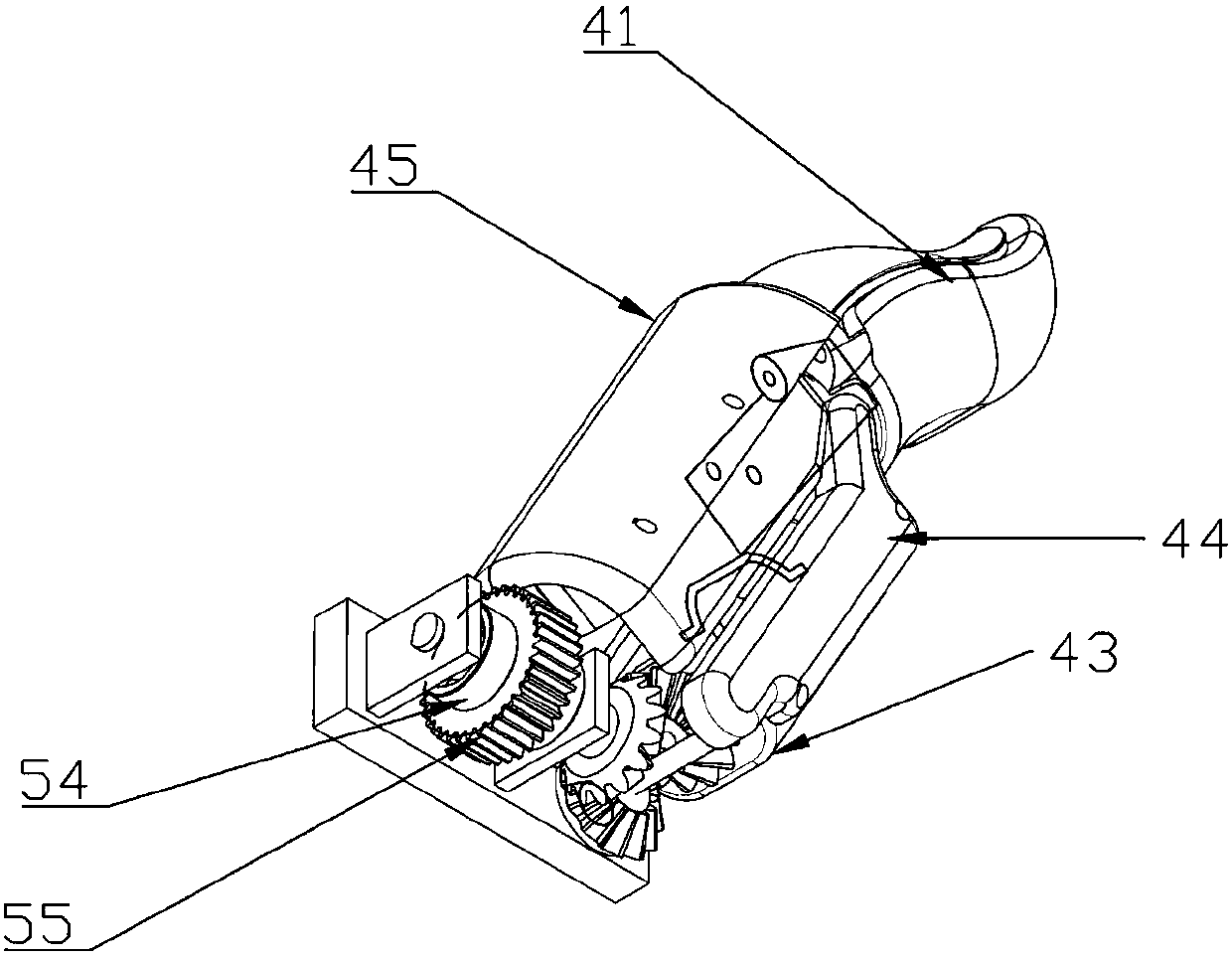
[0072] see Figure 1 to Figure 8 , the present invention discloses a thumb module of a mechanical bionic hand, comprising a thumb mechanism 4 , a thumb drive unit 46 , and a thumb planetary gear transmission mechanism 5 .
[0073] Described thumb mechanism 4 comprises thumb far knuckle 41, thumb far joint 42, thumb rotating motor base middle part 43, thumb rotating motor base side plate 44, thumb near knuckle shell 45, motor fixing belt 47, First bevel gear 48, transmission plate 49.
[0074] Described thumb mechanism 4 comprises differential coupling mechanism, and described differential coupling mechanism is the mechanism that makes thumb bend, and refers to thumb mechanism 4 except thumb far knuckle 41, most parts of fixing band 47, including thumb Far joint 42, thumb rotating motor base middle part 43, thumb proximal knuckle shell 45, thumb rotating motor 46, first bevel gear 48, transmission plate 49.
[0075] Described thumb drive unit is fixed on the thumb base middle...
Embodiment 2
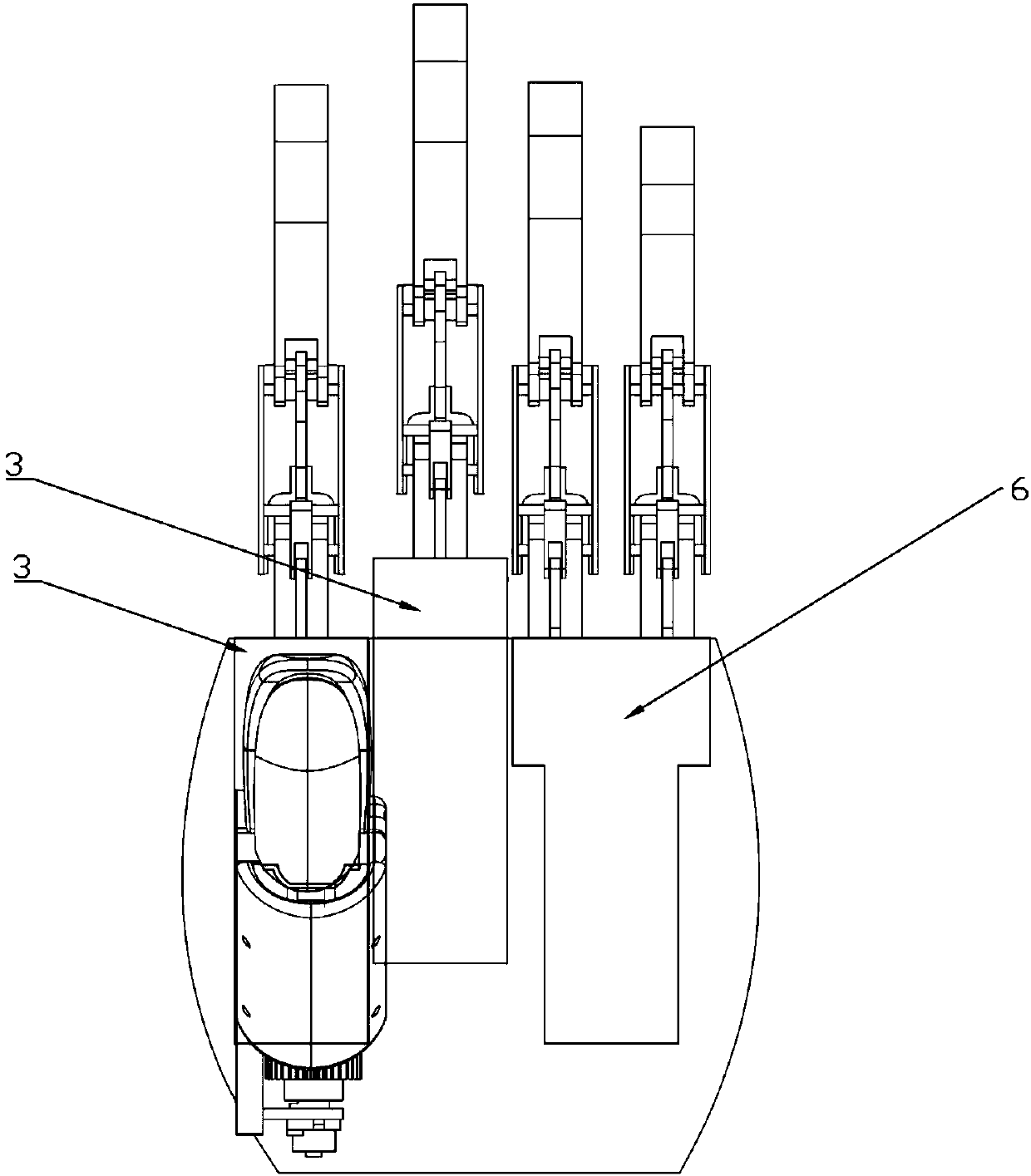
[0085] see figure 1 , the invention discloses a mechanical bionic hand. The so-called underactuation means that the number of independent drivers in the system is less than the number of degrees of freedom. The mechanical bionic hand includes a wrist and a manipulator part; the manipulator part includes two first modular fingers, two first modular finger drive mechanisms, a second modular finger, a second modular finger drive mechanism, a thumb Mechanism, thumb planetary gear transmission mechanism.
[0086] The first modular finger 1 includes a modular finger, and the second modular finger includes two modular fingers; the two first modular fingers are used for bionic index finger and middle finger respectively, and the second modular finger is used for Bionic ring finger and little finger, the thumb mechanism is used for bionic thumb.
[0087] Each first modular finger driving mechanism is connected to the corresponding first modular finger to drive the action of the first...
Embodiment 3
[0104] A thumb module of a mechanical bionic hand comprises a thumb mechanism, a thumb drive unit, and an integral rotation transmission mechanism. The thumb mechanism 4 includes a thumb distal knuckle, a thumb distal joint, and a thumb proximal knuckle shell, and the thumb distal knuckle and the thumb proximal knuckle shell are connected through the thumb distal joint.
[0105] The thumb mechanism includes a far knuckle rotation and bending transmission mechanism (differential drive mechanism); the thumb drive unit is connected to the thumb far joint through the far knuckle rotation and bending transmission mechanism, and can drive the rotation of the thumb far knuckle , causing the thumb to flex.
[0106] The thumb drive unit is connected to the thumb proximal knuckle shell 45 through the integral rotation transmission mechanism, and drives the thumb mechanism 4 to rotate as a whole.
PUM
 Abstract
Description
Claims
Application Information
 - R&D
- Intellectual Property
- Life Sciences
- Materials
- Tech Scout
- Unparalleled Data Quality
- Higher Quality Content
- 60% Fewer Hallucinations
Browse by: Latest US Patents, China's latest patents, Technical Efficacy Thesaurus, Application Domain, Technology Topic, Popular Technical Reports.
© 2025 PatSnap. All rights reserved.Legal|Privacy policy|Modern Slavery Act Transparency Statement|Sitemap|About US| Contact US: help@patsnap.com