Servo power cutter tower

A technology of powered turrets and cutterheads, which is applied in the field of turrets and can solve problems such as increasing costs

Pending Publication Date: 2019-10-18
PINGHU HAICHEN MACHINE
View PDF0 Cites 7 Cited by
  • Summary
  • Abstract
  • Description
  • Claims
  • Application Information

AI Technical Summary

Problems solved by technology

The bed part is the main part of the machine tool as a whole, and the increase in the size of the bed will directly increase the cost

Method used


Image

  • Servo power cutter tower
  • Servo power cutter tower
  • Servo power cutter tower

Examples


Embodiment Construction

[0020] Embodiments of the present invention will be described in detail below in conjunction with the accompanying drawings.

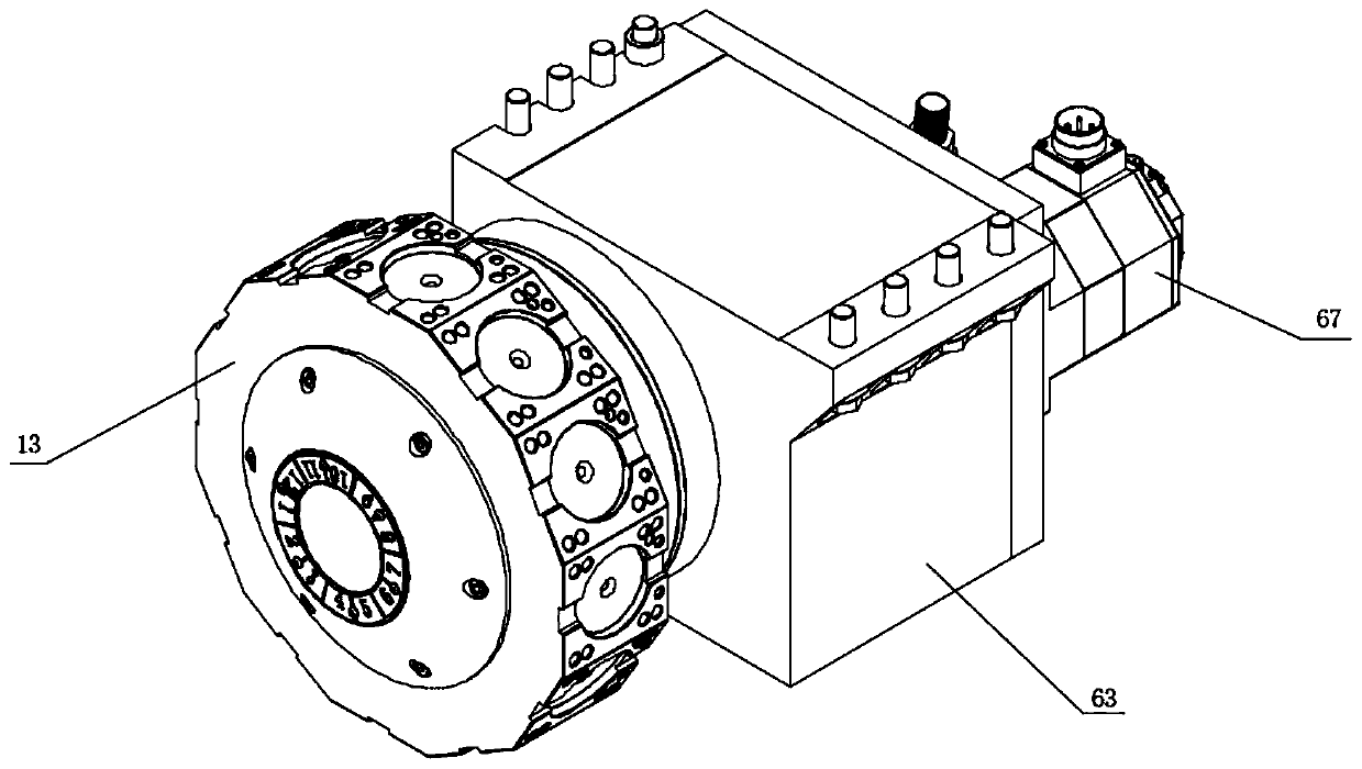
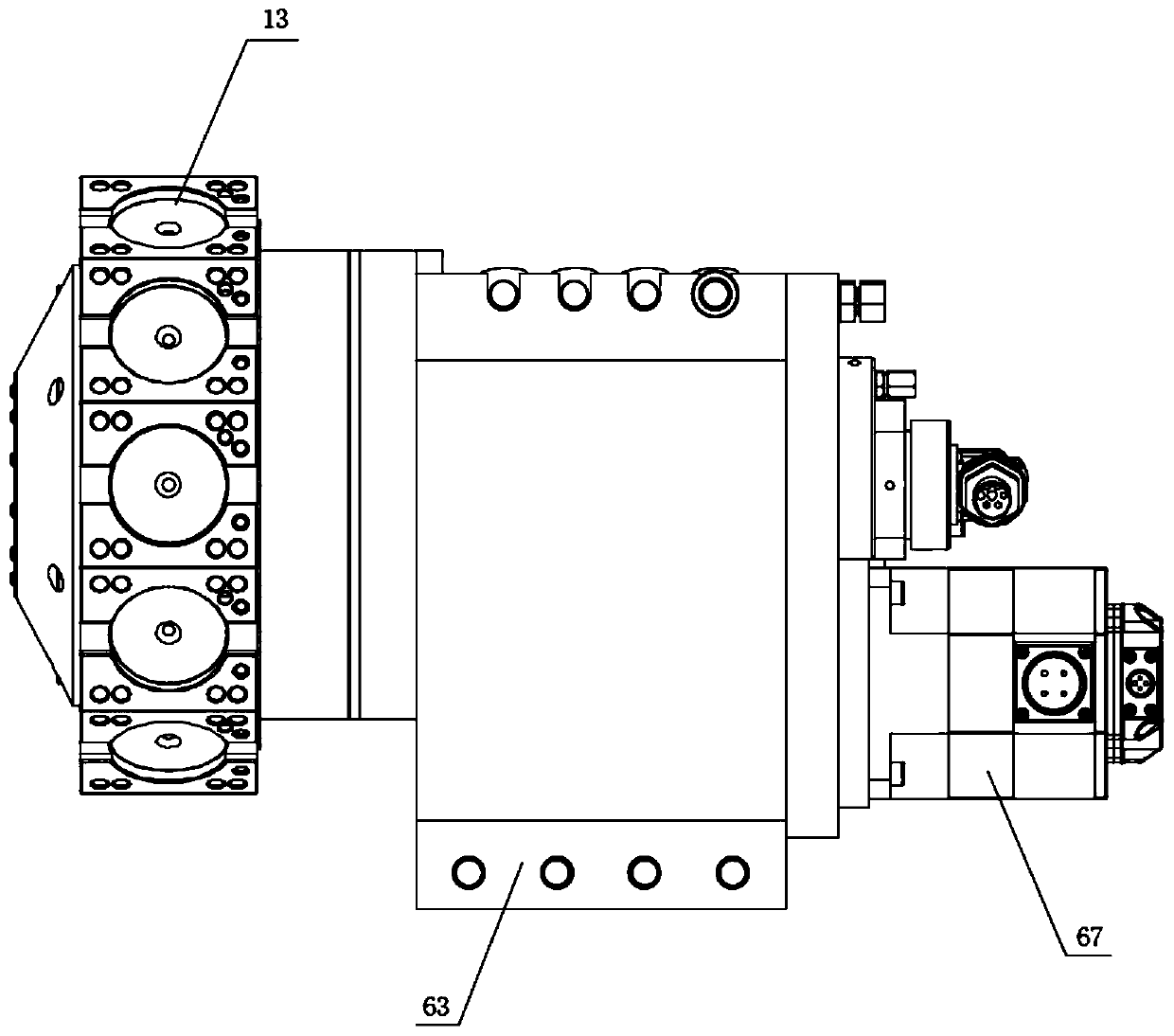
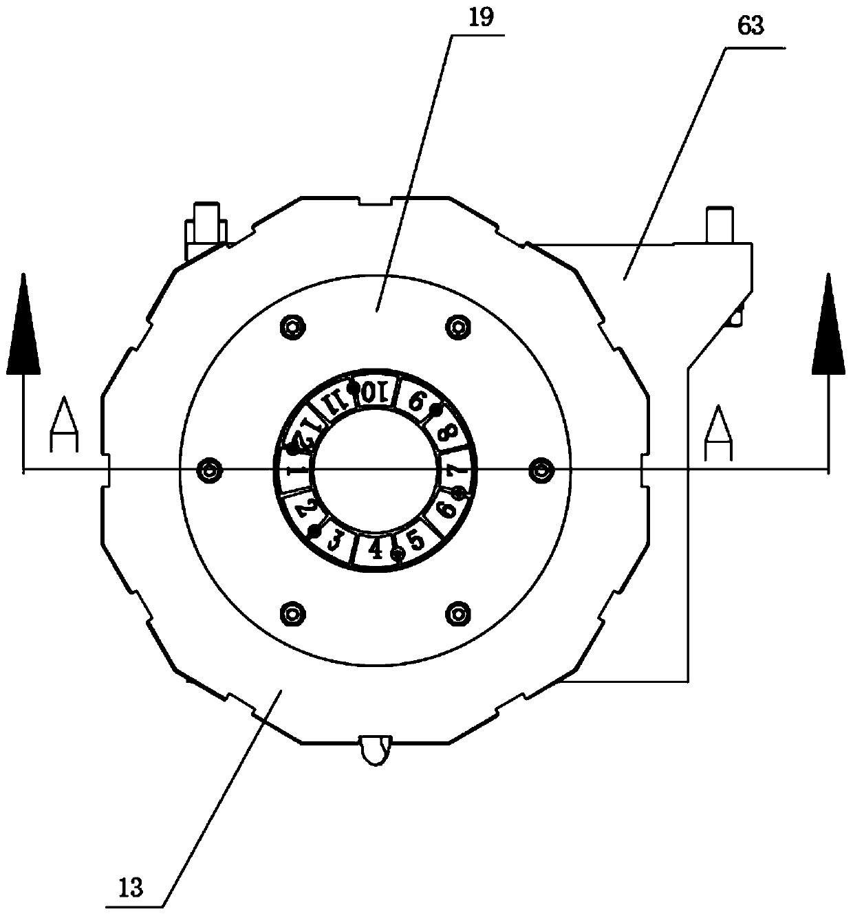
[0021] Such as Figure 1-4 As shown, a servo power turret includes a box body 63, a cutterhead 13 and a motor 67, the cutterhead 13 and the motor 67 are located on the box body 63, and the cutterhead 13 is rotationally connected with the box body 63; There is a central shaft 54 ​​and a gear 39, the gear 39 is sleeved on the central shaft 54, and the gear 39 is slidably connected with the central shaft 54, and the gear 39 is connected with the motor 67; the casing 63 is also provided with a rotating toothed disc 28 and a positioning toothed disc 30 and the moving toothed plate 33, the moving toothed plate 33 is socketed on the gear 39, the rotating toothed plate 28 is socketed on the central shaft 54, the positioning toothed plate 30 is socketed on the rotating toothed plate 28; the moving toothed plate 33 is simultaneously with the positioning The too...


PUM


Abstract

A servo power cutter tower comprises a box body, a cutter head and a motor. The cutter head and the motor are located on the box body, and the cutter head is rotationally connected with the box body.A central shaft and a gear are arranged in the box body, the gear is in sleeving connection with the central shaft, the gear is rotated around the central shaft, and the gear is driven by the motor through a transmission gear and a reduction device; and a rotating gear disc, a positioning gear disc and a moving gear disc are further arranged in the box body, the moving gear disc is in sleeving connection with the gear, the rotating gear disc is in sleeving connection with the central shaft, and the positioning gear disc is in sleeving connection with the rotating gear disc. Compared with the prior art, the cutter head is driven to rotate under the effect of the rotating gear disc, therefore, a main shaft in the cutter head can correspond to different cutter installation holes in the cutterhead, the cutter replacement effect is achieved, the rotating gear disc can be engaged with the moving gear disc when cutters are not changed and after the cutter are replaced, stability of the rotating gear disc is improved, the number of teeth of the rotating gear disc is matched with that of the cutter installation holes, and using convenience of the cutter head is ensured.

Description

technical field [0001] The invention belongs to the technical field of turrets, in particular to a servo power turret. Background technique [0002] The traditional turret structure currently in use mainly uses a servo motor to drive the cutter head to rotate through the reducer to select the tool, and an external motor drives the tool spindle to rotate through the mechanical transmission structure for cutting. The traditional turret has a complex structure and requires installation of components. The space is large, the volume of the turret is large, the overall size is too long, and there is an extra transmission link if there are more reducers. The transmission accuracy is low, the transmission gap is large, and the cost is high. At the same time, the power transmission chain limits the speed and speed of the tool shaft. Torque seriously restricts the overall machining performance of the machine tool. As for the overall design of the machine tool, because the length of t...

Claims


Application Information

Patent Timeline
Patent Type & Authority Applications(China)
IPC IPC(8): B23B29/32B23Q3/155
CPCB23B29/32B23Q3/15526
Inventor 胡晓东姚向东邹运姚洁
Owner PINGHU HAICHEN MACHINE
Why Eureka
Try Eureka