
Array substrate, display panel and display device

An array substrate and electrical connection technology, applied in the display field, can solve problems such as current changes, affecting display effects, and differences between display brightness and ideal brightness

Inactive Publication Date: 2019-10-15
WUHAN TIANMA MICRO ELECTRONICS CO LTD
View PDF9 Cites 19 Cited by
  • Summary
  • Abstract
  • Description
  • Claims
  • Application Information

AI Technical Summary

Problems solved by technology

[0003] In the pixel circuit of an Active-Matrix Organic Light Emitting Diode (AMOLED), there is a coupling capacitance between the wiring connected to the gate of the drive transistor and the data signal line. Since the OLED is a current-driven element, the existence of the coupling capacitance It will cause the current flowing through the OLED to change, resulting in a difference between the actual display brightness and the ideal brightness, affecting the display effect

Method used


Image

  • Array substrate, display panel and display device
  • Array substrate, display panel and display device
  • Array substrate, display panel and display device

Examples


Embodiment Construction

[0027] The present invention will be further described in detail below in conjunction with the accompanying drawings and embodiments. It should be understood that the specific embodiments described here are only used to explain the present invention, but not to limit the present invention. In addition, it should be noted that, for the convenience of description, only some structures related to the present invention are shown in the drawings but not all structures.

[0028] Terms used in the embodiments of the present invention are only for the purpose of describing specific embodiments, and are not intended to limit the present invention. It should be noted that the orientation words such as "up", "down", "left", and "right" described in the embodiments of the present invention are described from the angles shown in the drawings, and should not be interpreted as a reference to the implementation of the present invention. Example limitations. Also in this context, it also nee...


PUM


Abstract

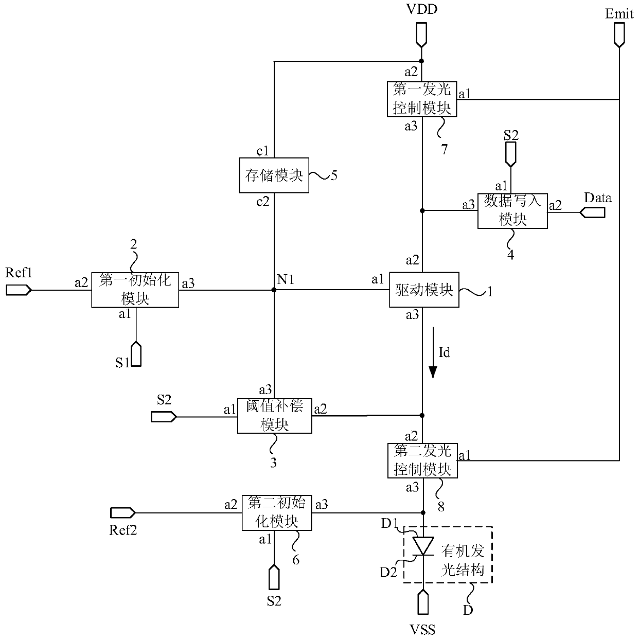
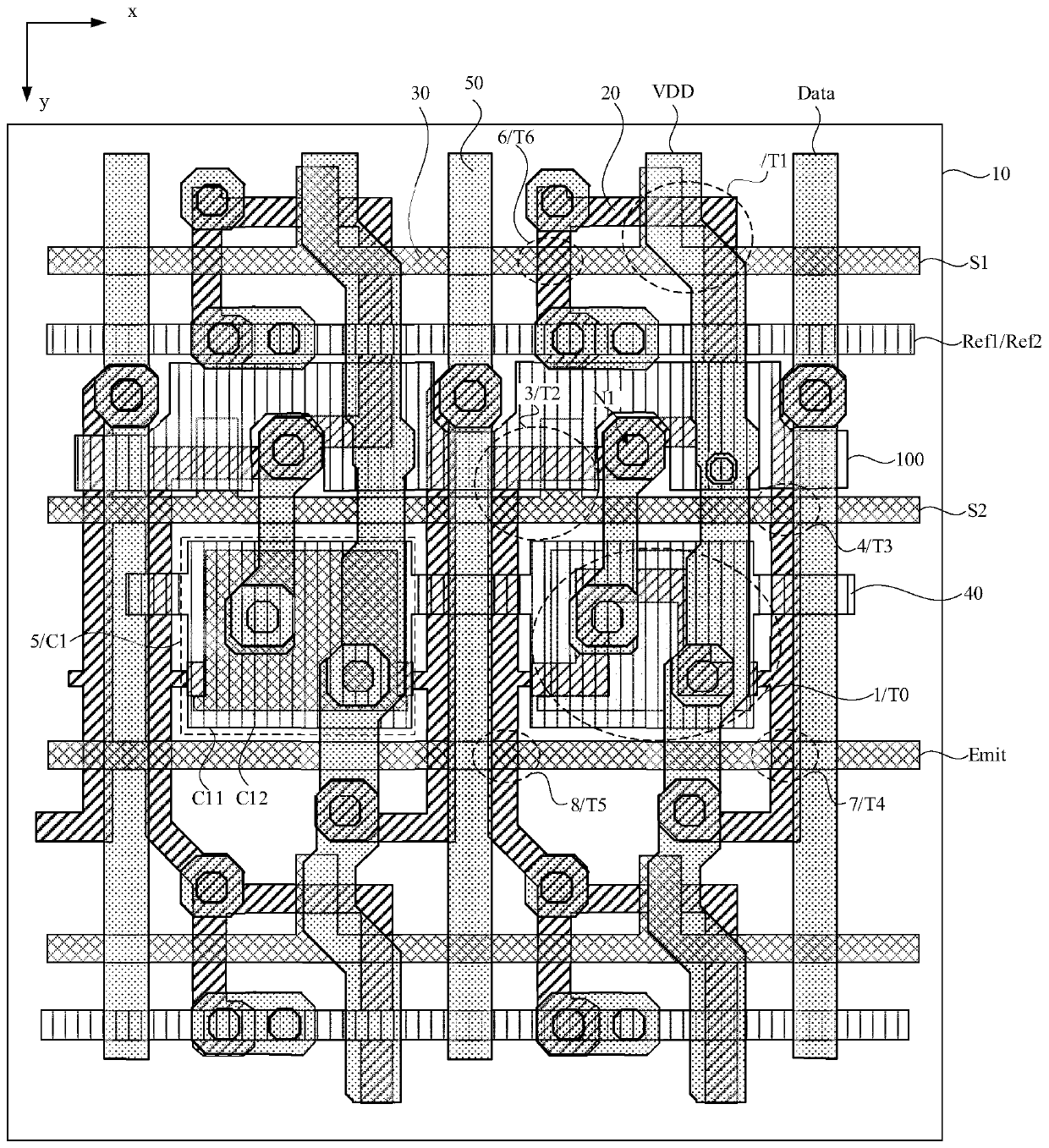
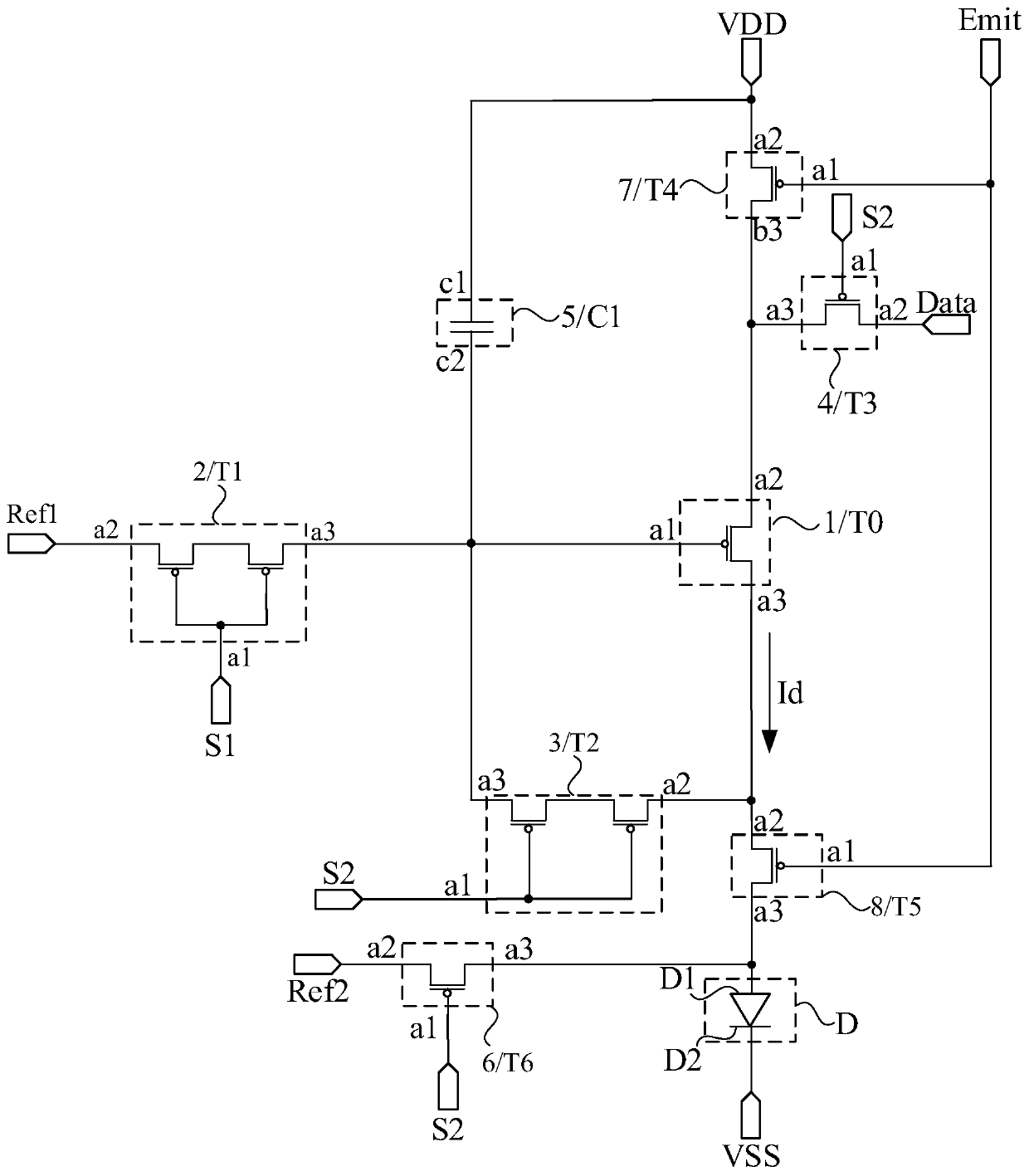
The embodiment of the invention discloses an array substrate, a display panel and a display device. The array substrate comprises a pixel circuit, the pixel circuit comprises a driving module, and thecontrol end of the driving module is electrically connected with a first node; a first initialization module, wherein a second end of the first initialization module is electrically connected with the first node; a threshold compensation module, wherein the second end of the threshold compensation module is electrically connected with the first node; a data writing module which is used for writing the data signal into the first node; a storage module, wherein the first end of the storage module is electrically connected with the first power supply signal line, and a second end of the storagemodule is electrically connected with the first node; the array substrate further comprises a shielding layer, the shielding layer is electrically connected with the first power signal line, and in the signal lines electrically connected with the first node, at least part of the signal lines and the shielding layer are overlapped in an insulated mode in the direction perpendicular to the plane where the array substrate is located. According to the technical scheme, crosstalk caused by coupling capacitance in the pixel circuit can be reduced, and the display effect is improved.

Description

technical field [0001] Embodiments of the present invention relate to display technologies, and in particular to an array substrate, a display panel and a display device. Background technique [0002] With the development of display technology, Organic Light Emitting Diode (OLED) displays have been more and more widely used in the display field due to their advantages such as active light emission, wide viewing angle, high contrast ratio, low power consumption, and fast response speed. , and gradually replace the traditional liquid crystal display (Liquid Crystal Display, LCD). [0003] In the pixel circuit of an Active-Matrix Organic Light Emitting Diode (AMOLED), there is a coupling capacitance between the wiring connected to the gate of the drive transistor and the data signal line. Since the OLED is a current-driven element, the existence of the coupling capacitance It will cause the current flowing through the OLED to change, resulting in a difference between the actua...

Claims


Application Information

Patent Timeline
Patent Type & Authority Applications(China)
IPC IPC(8): G09G3/3208G09G3/3225G09G3/3233H01L27/32
CPCG09G3/3208G09G3/3225G09G3/3233H10K59/126
Inventor 柴慧平韩立静
Owner WUHAN TIANMA MICRO ELECTRONICS CO LTD
Learn More