Curved-surface thin-wall part vibration control device based on permanent magnet driving
A permanent magnet drive, thin-walled technology, applied in transmission, non-rotational vibration suppression, belt/chain/gear, etc., can solve the problem of insufficient torque transmission accuracy, saving driving source, high output rigidity, reducing power consumption. The effect of small magnetic leakage
- Summary
- Abstract
- Description
- Claims
- Application Information
AI Technical Summary
Problems solved by technology
Method used
Image
Examples
Embodiment 1
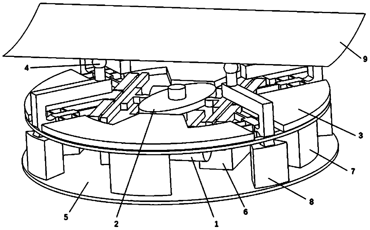
[0053] like Figure 1 to Figure 6As shown, a vibration control device for curved thin-walled parts based on permanent magnet drive includes an electromagnetic permanent magnet drive mechanism 1, a driven mechanism 2, a motion conversion mechanism 3, and an adaptive support mechanism 4; the electromagnetic permanent magnet drive mechanism 1 passes The first fixed auxiliary assembly (specifically the fixed block 6) is installed on the base 5, the motion transformation mechanism 3 is installed on the base 5 through the second fixed auxiliary assembly (including the first fixed column 7 and the second fixed column 8), and the electromagnetic permanent The magnetic drive mechanism 1 is connected to the driven mechanism 2 and provides power source to the driven mechanism 2; the driven mechanism 2 is connected to the motion transformation mechanism 3, and the motion transformation mechanism 3 converts the reciprocating motion of the driven mechanism 2 into a vertical motion; the motio...
Embodiment 2
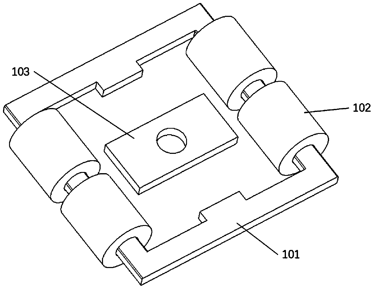
[0066] like Figure 7 to Figure 10 As shown, this embodiment is consistent with Embodiment 1 in terms of driving principle, electromagnetic coil design, etc., and the main change is the design of the motion conversion mechanism 3, which adopts a polygonal tensioning structure 301 based on elastic materials.
[0067] A vibration control device for curved thin-walled parts based on permanent magnet drive, comprising an electromagnetic permanent magnet drive mechanism 1, a driven mechanism 2, a motion transformation mechanism 3, and an adaptive supporting mechanism 4; the electromagnetic permanent magnet drive mechanism 1 and the motion transformation mechanism 3 is installed on the base 5, the electromagnetic permanent magnet driving mechanism 1 is connected with the driven mechanism 2, and provides power source to the driven mechanism 2; The motion is converted into a vertical motion; the motion transformation mechanism 3 is connected to the self-adaptive support mechanism 4 , ...
Embodiment 3
[0073] like Figure 9 to Figure 13 As shown, this embodiment is consistent with Embodiment 2 in terms of driving principle, electromagnetic coil design, etc. The main change is the design of the motion conversion mechanism 3, which adopts a disc structure with a boss.
[0074]A vibration control device for curved thin-walled parts based on permanent magnet drive, comprising an electromagnetic permanent magnet drive mechanism 1, a driven mechanism 2, a motion transformation mechanism 3, and an adaptive supporting mechanism 4; the electromagnetic permanent magnet drive mechanism 1 and the motion transformation mechanism 3 is installed on the base 5, the electromagnetic permanent magnet driving mechanism 1 is connected with the driven mechanism 2, and provides power source to the driven mechanism 2; The motion is converted into a vertical motion; the motion transformation mechanism 3 is connected to the self-adaptive support mechanism 4 , and the self-adaptive support mechanism 4...
PUM
 Abstract
Description
Claims
Application Information
 - R&D
- Intellectual Property
- Life Sciences
- Materials
- Tech Scout
- Unparalleled Data Quality
- Higher Quality Content
- 60% Fewer Hallucinations
Browse by: Latest US Patents, China's latest patents, Technical Efficacy Thesaurus, Application Domain, Technology Topic, Popular Technical Reports.
© 2025 PatSnap. All rights reserved.Legal|Privacy policy|Modern Slavery Act Transparency Statement|Sitemap|About US| Contact US: help@patsnap.com


