Spherical tensile steel support and multi-angle load dispersion method

A tensile steel, spherical technology, applied in bridge parts, bridges, buildings and other directions, can solve the problems of many parts coordination, complex structural design, stress concentration, etc., to achieve stable and reliable structural stress, reasonable structural design, Avoid the effect of stress concentration

Pending Publication Date: 2019-10-15
单国珠
View PDF0 Cites 2 Cited by
  • Summary
  • Abstract
  • Description
  • Claims
  • Application Information

AI Technical Summary

Problems solved by technology

But at the same time, some tensile bearings have defects in structural design and calculation. For example, when the upper and lower structures of the bearing produce the tensile function, the two contact surfaces are in line contact or point contact, especially for the vertical pullout force. , in extreme cases (such as earthquakes), when the rotation angle of the support exceeds the design angle, it is easy to cause stress concentration; on the other hand, although some tensile supports solve the problem of stress concentration, the structural design is more complicated and the parts are coordinated. There are many fits, the support is bulky and the weight is high, so it is difficult to popularize and apply it in actual engineering projects

Method used


Image

  • Spherical tensile steel support and multi-angle load dispersion method
  • Spherical tensile steel support and multi-angle load dispersion method

Examples


Embodiment Construction

[0024] The present invention will be further explained below in conjunction with the accompanying drawings and specific embodiments. It should be understood that the following specific embodiments are only used to illustrate the present invention and are not intended to limit the scope of the present invention. In the description of the present invention, it should be noted that the terms "center", "upper", "lower", "left", "right", "vertical", "horizontal", "inner", "outer", The orientation or positional relationship indicated by "top", "bottom", etc. are based on the orientation or positional relationship shown in the drawings, and are only for the convenience of describing the present invention and simplifying the description, rather than indicating or implying that the referred device or element must have Certain orientations, constructed and operative in certain orientations, therefore are not to be construed as limitations on the invention. In addition, unless otherwise ...


PUM


Abstract

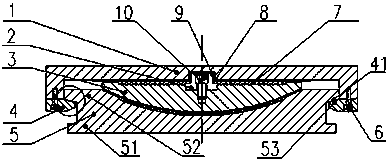
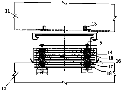
The invention belongs to the technical field of bridge supports and particularly relates to a spherical tensile steel support and a multi-angle load dispersion method. The main technical scheme is asfollows: the support comprises an upper support plate, a lower support plate, a spherical crown lining plate, a convex-shaped structure guide rail strip and arc-shaped pressing plates with arc-shapedstructures; the upper support plate can be fixedly connected with a beam body, the lower support plate can be fixedly connected with piers and the upper plate surface of the lower support plate is ina spherical concave shape; and the spherical crown lining plate is arranged between the upper support plate and the lower support plate, the upper plate surface of the spherical crown lining plate isa plane, and the lower plate surface of the spherical crown lining plate is a corresponding spherical surface. The arc-shaped pressing plates are fixed on the flange lower plate surfaces of the two sides of the upper support plate, wherein the upper side face of the arc-shaped pressing plate is an inner arc surface, and the inner arc surfaces of the arc-shaped pressing plates are directly buckledon the arc-shaped side face, which is of an inverted table shape, of the lower support plate, and the center of the spherical surface of the lower plate surface of the spherical crown lining plate coincides with the center of the arc surfaces of the arc-shaped pressing plates. According to the structure in the invention, contact stress with concentrated stress is effectively overcome, so that thestructure stress is stable and reliable, the stress of the bridge structure is improved, and the service life of the support is prolonged.

Description

technical field [0001] The invention relates to the field of components used for bridge engineering support, in particular to a spherical tensile steel support and a method for dispersing loads at multiple angles. Background technique [0002] The support is an important part connecting the upper beam structure and the lower pier column structure in bridge engineering. Its basic function is to transfer the upper load of the structure to the lower structure through the support, while ensuring the required force and displacement of the structure. . Therefore, in general, it is required to have vertical bearing capacity, horizontal bearing capacity or displacement characteristics in the bearing design. In most cases, the support has the above functions to meet the needs of engineering design. However, in some occasions, tension will appear at individual fulcrums of the structure, and the foundation will settle due to geological or construction reasons. At this time, the suppo...

Claims


Application Information

Patent Timeline
Patent Type & Authority Applications(China)
IPC IPC(8): E01D19/04
CPCE01D19/04E01D19/042E01D19/046
Inventor 崔鹏飞单国珠王忠涛苏仝柱张露赵利文戴玉东
Owner 单国珠
Why Eureka
Try Eureka