Eureka AIR delivers breakthrough ideas for toughest innovation challenges, trusted by R&D personnel around the world.

Low-energy-consumption assembly type component maintenance shed and operation method thereof

A curing shed and assembled technology, which is applied in the direction of auxiliary molding equipment, ceramic molding machines, manufacturing tools, etc., can solve the problems of lack of smoke exhaust facilities, high fire risk in the curing shed, and high temperature of hot air from electric heaters

Pending Publication Date: 2019-10-15
CHINA RAILWAY CONSTR GROUP +1
View PDF0 Cites 3 Cited by
  • Summary
  • Abstract
  • Description
  • Claims
  • Application Information

AI Technical Summary

Problems solved by technology

However, the on-site maintenance room of the prior art can only maintain small concrete specimens, but cannot maintain large concrete prefabricated components, and the energy consumption is relatively high
[0007] In addition, the maintenance sheds on the construction site are generally built with flammable light materials, and temporary power lines are erected, and are heated by high-temperature electric heaters. The power load is large, and the 24-hour continuous operation poses a high risk of cable heating.
And the hot air temperature of the electric heater is very high
Therefore, the fire risk of the maintenance shed at the construction site is extremely high
Moreover, since the automatic sprinkler fire-fighting pipe network, pump group, and control center of the building under construction have not yet been completed, the maintenance shed lacks reliable automatic fire-extinguishing facilities
[0008] In addition, the maintenance shed operates 24 hours a day, and the personnel on duty at night are sleepy and slow to respond to emergencies, so it is often difficult to evacuate quickly when a fire occurs
However, the existing maintenance shed lacks reliable smoke exhaust facilities to prevent the evacuation mouth from being blocked by smoke, and also to buy time for the safe evacuation of personnel

Method used


Image

  • Low-energy-consumption assembly type component maintenance shed and operation method thereof
  • Low-energy-consumption assembly type component maintenance shed and operation method thereof

Examples


Embodiment Construction

[0064] The following will clearly and completely describe the technical solutions in the embodiments of the present invention with reference to the accompanying drawings in the embodiments of the present invention. Obviously, the described embodiments are only some, not all, embodiments of the present invention. Based on the embodiments of the present invention, all other embodiments obtained by persons of ordinary skill in the art without making creative efforts belong to the protection scope of the present invention.

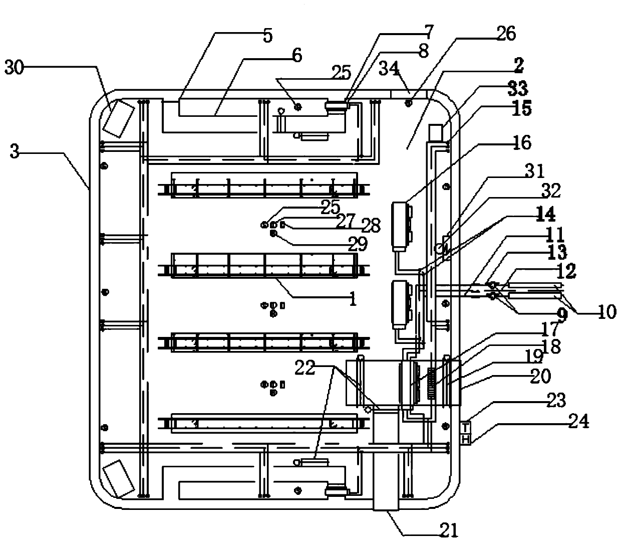
[0065] see Figure 1~2 , a low-energy-consumption assembly-type component maintenance shed, including a maintenance shed, a prefabricated assembly-type component 1 is arranged inside the maintenance shed, and the prefabricated assembly-type component 1 is an integrated assembly-type component of a steel bar formwork, and the prefabricated assembly-type component 1 is provided with a high heat capacity concrete floor 2, and the outside of the high heat capacity...


PUM


Abstract

The invention discloses a low-energy-consumption assembly type component maintenance shed and an operation method thereof. A maintenance shed is included and is internally provided with a prefabricated assembly type component. The prefabricated assembly type component is a rebar template integration assembly type component. A high-heat-capacity concrete floor is arranged on the outer side of the prefabricated assembly type component, and the outside of the high-heat-capacity concrete floor is coated with an air bag thermal insulating wall. The low-energy-consumption assembly type component maintenance shed and the operation method thereof have the beneficial effects that the problems under extreme weather conditions, an assembly type component is produced in the engineering field, maintenance temperature fluctuation is large, energy consumption is high, a maintenance shed is large in fire danger and lacks automatic fire extinguishing installations, and people evacuation is difficult can be solved.

Description

technical field [0001] The invention relates to a prefabricated component maintenance shed, in particular to a low-energy consumption prefabricated component maintenance shed and an operation method thereof, belonging to the technical field of prefabricated concrete buildings. Background technique [0002] Prefabricated concrete buildings refer to concrete structure buildings designed and constructed through on-site assembly of reinforced concrete prefabricated components mainly produced in factories. It is generally divided into two categories: fully assembled buildings and partially assembled buildings: fully assembled buildings are generally low-rise or multi-storey buildings with low seismic fortification requirements; the main components of partially assembled buildings are generally prefabricated components, which are connected by cast-in-place concrete on site. A building that forms an assembled monolithic structure. The characteristics of the building are that the c...

Claims


Application Information

Patent Timeline
Patent Type & Authority Applications(China)
IPC IPC(8): B28B11/24B28B17/00
CPCB28B11/245B28B11/247B28B17/0063
Inventor 王宽周大兴武利平李长勇陈静钟文杰田菲郭伟秦亚淼黄远珍徐向军张亚齐温恺史乐贤
Owner CHINA RAILWAY CONSTR GROUP
Why Eureka
Eureka Blog
Learn More