
Movable new energy solar power generation equipment

A technology that facilitates movement and power generation equipment, applied in solar thermal power generation, mobile/directional solar collectors, solar thermal energy, etc., can solve problems such as inconvenient movement, waste of manpower and material resources, and reduced work efficiency, so as to maintain stability and prevent The effect of being damaged and increasing the service life

Active Publication Date: 2019-10-11
CRCC HARBOR & CHANNEL ENG BUREAU GRP
View PDF2 Cites 3 Cited by
  • Summary
  • Abstract
  • Description
  • Claims
  • Application Information

AI Technical Summary

Problems solved by technology

[0003] However, the existing solar power generation equipment is fixed on the ground. When it needs to be adjusted or overhauled, it needs to be carried by manpower, which is very inconvenient to move, wastes manpower and material resources, and reduces work efficiency. , to judge the overall working status of multiple solar panels, but it is impossible to directly determine the position or approximate range of the damaged solar panel. This application only relies on the specially designed position and the output The overall power signal can directly determine the location or approximate range of the damaged solar panel

Method used


Image

  • Movable new energy solar power generation equipment
  • Movable new energy solar power generation equipment
  • Movable new energy solar power generation equipment

Examples


Embodiment Construction

[0026] The technical solutions of the present invention will be further described below in conjunction with the accompanying drawings and through specific implementation methods.

[0027] Wherein, the accompanying drawings are only for illustrative purposes, showing only schematic diagrams, rather than physical drawings, and should not be construed as limitations on this patent; in order to better illustrate the embodiments of the present invention, some parts of the accompanying drawings will be omitted, Enlargement or reduction does not represent the size of the actual product; for those skilled in the art, it is understandable that certain known structures and their descriptions in the drawings may be omitted.

[0028] In the drawings of the embodiments of the present invention, the same or similar symbols correspond to the same or similar components; , "inner", "outer" and other indicated orientations or positional relationships are based on the orientations or positional ...


PUM


Abstract

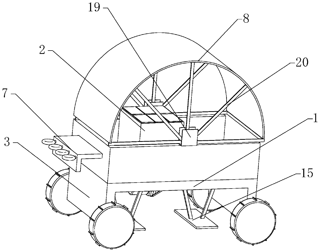
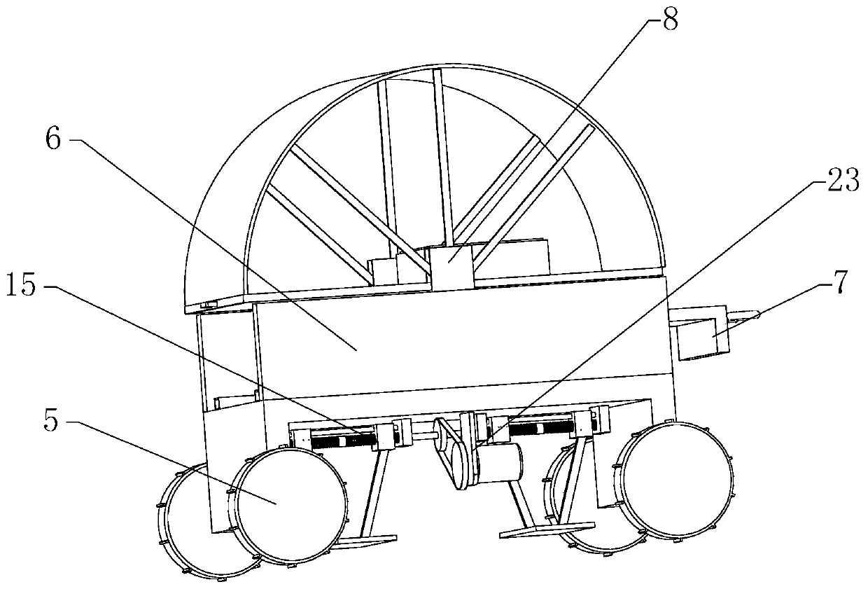
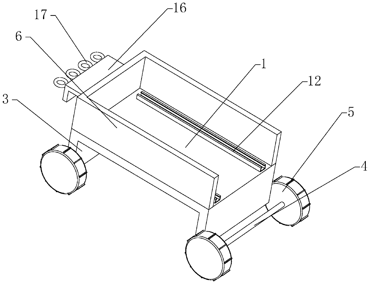
The invention relates to the technical field of the new energy equipment, and specifically relates to movable new energy solar power generation equipment. The movable new energy solar power generationequipment comprises a mounting plate, a movement mechanism and a power generation mechanism; fixed plates are arranged at two sides of the mounting plate; the movement mechanism comprises third rotating shafts and rollers; the third rotating shafts are horizontally coupled at the bottom of the fixed plates, and the rollers are fixedly arranged at two ends of the third rotating shafts; a limitingplate is further arranged on the mounting plate; a traction mechanism is fixedly arranged at a front end of the limiting plate; the power generation mechanism comprises a mounting table, a baseplate and multiple solar energy panels; a sliding rail is arranged on the mounting plate, a sliding block is arranged at the bottom of the baseplate, the sliding block is connected to the sliding rail in a sliding manner, and the mounting table is detachably arranged on the baseplate; multiple mounting slots are arranged at the top of the mounting table, the solar energy panels are arranged in the mounting slots, and a stabilization module is further arranged at the bottom of the mounting plate. The device is convenient to move, and the applicability of the device is improved.

Description

technical field [0001] The invention relates to the technical field of new energy equipment, in particular to a convenient mobile new energy solar power generation equipment. Background technique [0002] The energy of solar energy comes from the outer celestial bodies of the earth. It is the huge energy released by the fusion of hydrogen nuclei in the sun at ultra-high temperature. Most of the energy needed by human beings comes directly or indirectly from the sun. The coal, Fossil fuels such as petroleum and natural gas are all formed by plants that convert solar energy into chemical energy through photosynthesis, and then are buried in the ground after a long geological period. Solar energy will become the global One of the main energy sources is the most primitive energy source. Almost all other energy sources on the earth come directly or indirectly from solar energy. To obtain electricity from solar energy, it needs to be realized through solar power generation equipme...

Claims


Application Information

Patent Timeline
IPC IPC(8): H02S10/40H02S20/30H02S40/00F24S30/00
CPCH02S10/40H02S20/30H02S40/00F24S30/00Y02E10/50Y02E10/47
Inventor 陆煦
Owner CRCC HARBOR & CHANNEL ENG BUREAU GRP
Learn More