Power switching method

A power switching and power supply technology, applied in emergency power supply arrangements, electrical components, circuit devices, etc., can solve the problem of mutual interference between two power supplies, and achieve the effect of saving control terminals and control circuits

Active Publication Date: 2021-09-17
GREE ELECTRIC APPLIANCES INC
View PDF4 Cites 0 Cited by
  • Summary
  • Abstract
  • Description
  • Claims
  • Application Information

AI Technical Summary

Problems solved by technology

[0004] The embodiment of the present invention provides a power supply switching method to at least solve the technical problem that the two power supplies are prone to mutual interference when dual power supplies are used in the related art

Method used


Image

  • Power switching method
  • Power switching method

Examples


Embodiment Construction

[0019] In order to make those skilled in the art better understand the solutions of the present invention, the technical solutions in the embodiments of the present invention will be clearly and completely described below with reference to the accompanying drawings in the embodiments of the present invention. Obviously, the described embodiments are only Embodiments are part of the present invention, but not all embodiments. Based on the embodiments of the present invention, all other embodiments obtained by persons of ordinary skill in the art without creative efforts shall fall within the protection scope of the present invention.

[0020] It should be noted that the terms "first", "second" and the like in the description and claims of the present invention and the above drawings are used to distinguish similar objects, and are not necessarily used to describe a specific sequence or sequence. It is to be understood that the data so used may be interchanged under appropriate ...


PUM


Abstract

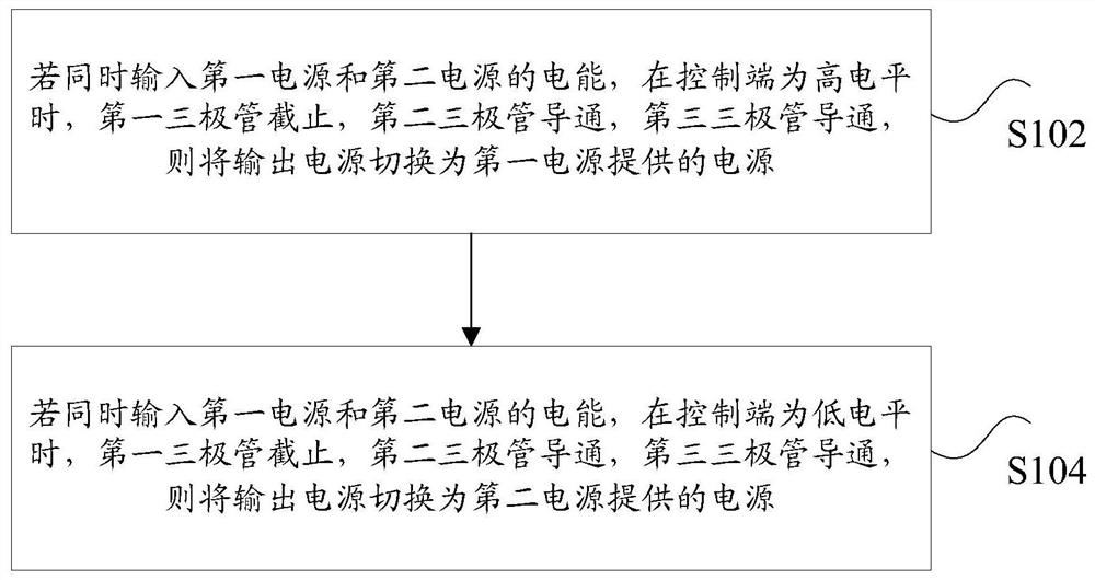
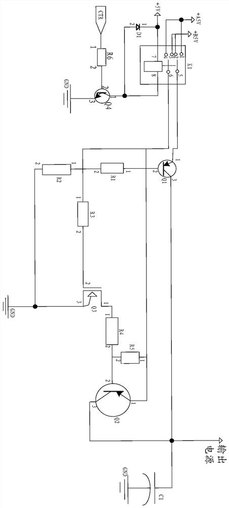
The invention discloses a power switching method. The power supply switching method is applied to the target control circuit. The target control circuit at least includes: a first power supply, a second power supply, a control terminal, a plurality of triodes and an output power supply, wherein the plurality of triodes at least includes: the first triode, the second three The power supply switching method includes: if the electric energy of the first power supply and the second power supply are input at the same time, when the control terminal is at a high level, the first triode is turned off, and the second triode is turned on , the third transistor is turned on, then the output power is switched to the power provided by the first power supply; if the electric energy of the first power supply and the second power supply are input at the same time, when the control terminal is at a low level, the first transistor is cut off, When the second triode is turned on and the third triode is turned on, the output power is switched to the power provided by the second power supply. The invention solves the technical problem that the two power sources are prone to mutual interference when dual power sources are used in the related art.

Description

technical field [0001] The present invention relates to the technical field of circuit control, and in particular, to a power switching method. Background technique [0002] In the related art, in a circuit with high power and heavy load, dual power supplies are generally used to realize the power saving function: one power supply is used for the operation of the controller, and the other power supply is used to control the power saving operation of the chip, which greatly reduces the power loss of the controller. When the controller is working normally, use a high-power power supply to maintain the operation of the controller and drive the load; when the controller does not need to work, enter power saving, use a low-power power supply, and only maintain the necessary work of the controller. However, this method of using dual power supplies for control often has the technical problem of mutual interference of the power supplies, which cannot guarantee the accuracy of power ...

Claims


Application Information

Patent Timeline
Patent Type & Authority Patents(China)
IPC IPC(8): H02J9/06
CPCH02J9/06H02J9/068
Inventor 李绍健金胜昔曾森张秋俊欧梦钦王浩良
Owner GREE ELECTRIC APPLIANCES INC
Why Eureka
Try Eureka