
Broadband dipole

A broadband dipole and reflector technology, applied in the field of broadband dipoles, can solve the problems of inability to realize broadband operation, difficult to miniaturize, narrow working bandwidth, etc., to simplify connection complexity, improve miniaturization, and widen working bandwidth. Effect

Pending Publication Date: 2019-10-11
PROSE TECH CO LTD
View PDF0 Cites 0 Cited by
  • Summary
  • Abstract
  • Description
  • Claims
  • Application Information

AI Technical Summary

Problems solved by technology

However, the height of the existing dipole is generally 1 / 4 wavelength of the center frequency point, and the profile is relatively high, so it is not easy to miniaturize. The radiating element is required to have sufficient size in the width direction, and the performance will be further deteriorated in the case of limited width and height

Method used


Image

  • Broadband dipole
  • Broadband dipole
  • Broadband dipole

Examples


Embodiment Construction

[0036] The technical solutions of the embodiments of the present invention will be clearly and completely described below in conjunction with the accompanying drawings of the present invention.

[0037] The broadband dipole disclosed by the invention adopts a curved surface conformal structure, which can effectively widen the working bandwidth of the antenna under the premise of reducing the width of the radiation unit.

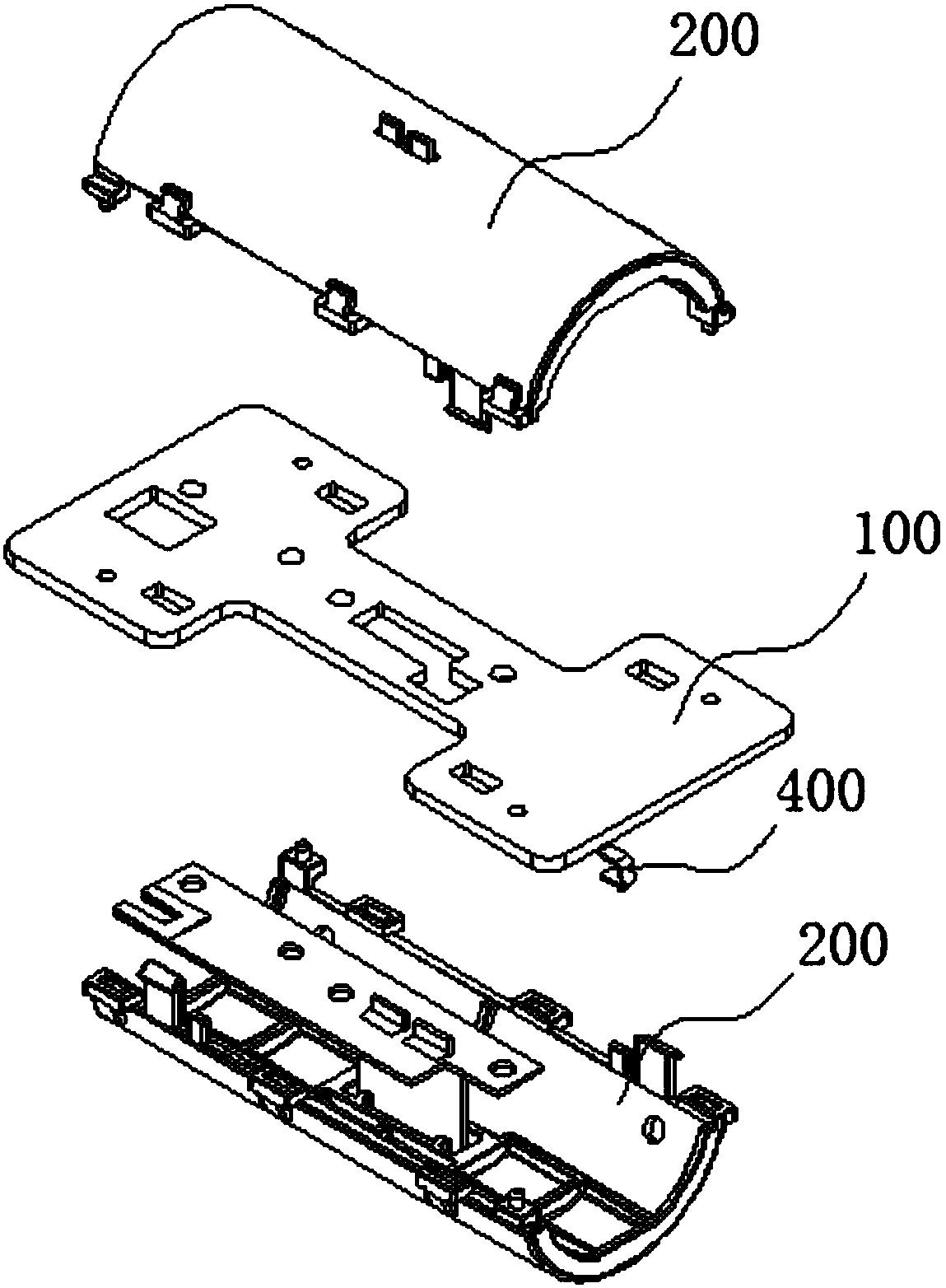
[0038] combine Figure 1 ~ Figure 4 As shown, a broadband dipole disclosed in the embodiment of the present invention includes a reflector 100 and two radiating units 200 symmetrically installed on the front and back sides of the reflector 100, and each radiating unit 200 includes a radiating element 201, The feeding balun 202 and the matching network 203 , the radiation component 201 is electrically connected to the matching network 203 through the feeding balun 202 , and the matching network 203 is fixed on the reflector 100 .

[0039] Specifically, such a...


PUM


Abstract

The invention discloses a broadband dipole. The broadband dipole comprises a reflection plate and a radiation unit installed on one side surface of the reflection plate. The radiation unit comprises aradiation assembly, a feed balun and a matching network. The radiation assembly is electrically connected with the matching network through the feed balun, the matching network is fixed on the reflection plate, and the radiation assembly is integrally of a curved surface structure arched towards the direction far away from the reflection plate. The radiation assembly comprises a flexible radiation base body and an insulating supporting piece, wherein the radiation base body is attached and fixed on the insulating supporting piece, and the insulating supporting piece is fixedly connected withthe reflecting plate. According to the invention, the effect of realizing broadband performance in an extremely small space can be achieved.

Description

technical field [0001] The invention relates to the field of mobile communication and is applied to an antenna network system, in particular to a broadband dipole used as a base station antenna. Background technique [0002] With the rapid development of the communication industry, the requirements for antenna performance are getting higher and higher. The antenna is required to have good matching and pattern characteristics in a limited space and a wide frequency band. So the current research focus is on broadband, miniaturization and so on. [0003] Among them, the dipole antenna has a series of advantages such as simple structure, stable performance, wide operating frequency range, and easy mass production, and has been widely used in antenna systems. However, the height of existing dipoles is generally 1 / 4 wavelength of the center frequency point, and the profile is relatively high, so it is not easy to miniaturize. The radiating element is required to have a sufficie...

Claims


Application Information

Patent Timeline
IPC IPC(8): H01Q1/38H01Q1/50H01Q9/28H01Q19/10
CPCH01Q1/38H01Q1/50H01Q9/28H01Q19/104
Inventor 董志峰孙静张妍
Owner PROSE TECH CO LTD
Learn More