Device for removing residual toner of toner cartridge through backflow cleaning

A toner cartridge and cleaning technology, applied in electrography, optics, instruments, etc., can solve problems such as imperfect technical considerations, affecting printing quality, inhaling toner, etc., to reduce environmental pollution, improve cleaning effect, and ensure health Effect

Inactive Publication Date: 2019-10-11
林丽芳
View PDF0 Cites 0 Cited by
  • Summary
  • Abstract
  • Description
  • Claims
  • Application Information

AI Technical Summary

Problems solved by technology

[0002] After the toner cartridge is used up, there is often some toner left inside. If the toner is not cleaned up and the toner is added directly, the added toner and the original toner may form solid blocks due to incompatibility, which will affect the printing quality. Therefore, before adding toner, be sure to clean up the toner in the original toner box. Generally, the toner is blown away by electric wind blowing, but the current technical considerations are not perfect, and it has the following disadvantages: the traditional electric wind blows directly The tuyere is aligned with the toner cartridge filling port to blow air, although the toner can be blown out, but the blown toner is scattered around, which seriously pollutes the surrounding environment, and it is easy to cause the operator to inhale the toner, endangering the health of the operator ; At the same time, after the blowing work is completed, the toner in the dead corners has not been completely removed, and the toner cartridge needs to be tapped several times by hand to see if there is any remaining powder. The vibration of the cartridge may easily cause the internal parts of the toner cartridge to fall off and cause damage to the toner cartridge, and the cleaning effect is average

Method used


Image

  • Device for removing residual toner of toner cartridge through backflow cleaning
  • Device for removing residual toner of toner cartridge through backflow cleaning
  • Device for removing residual toner of toner cartridge through backflow cleaning

Examples


Embodiment

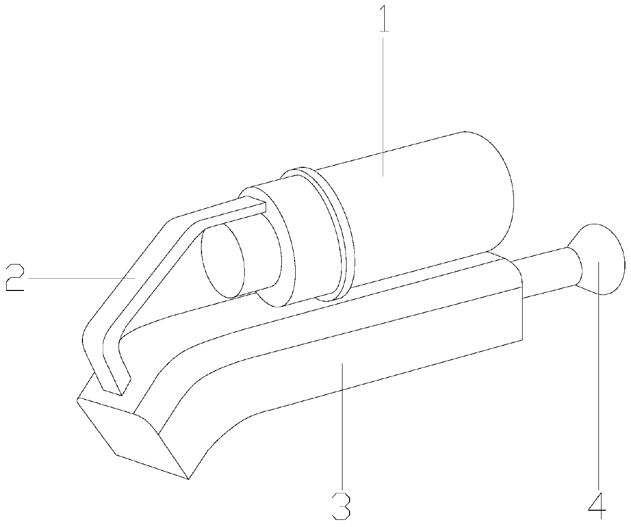
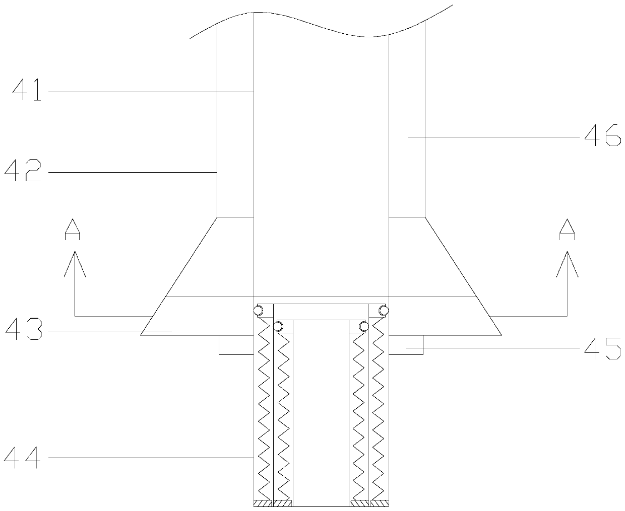
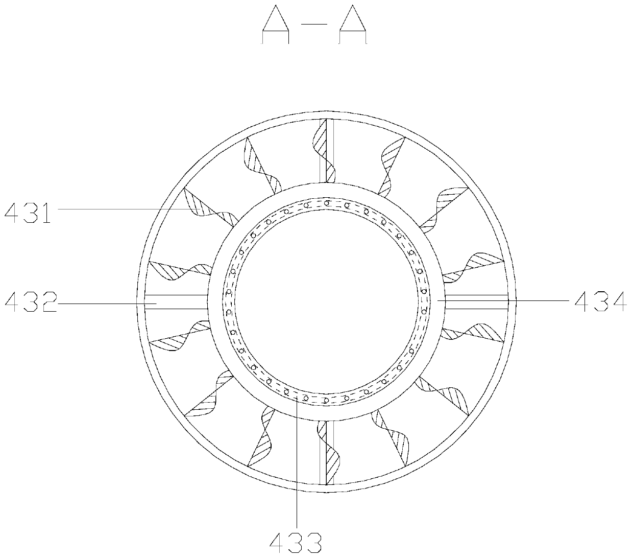
[0029] see Figure 1-Figure 2 , the present invention provides a toner cartridge residual powder removal device using backflow cleaning, its structure includes a toner collection box 1, an operating handle 2, a removal fan 3, a toner remover 4, the bottom of the operating handle 2 is connected to the removal The upper surface of the fan 3 is fixed together by bolts, the left end of the toner remover 4 is mechanically connected to the fan in the removal fan 3, the toner collection box 1 is a cylindrical structure and the left end is connected to the right end of the operating handle 2, Described toner remover 4 is made up of blower duct 41, remover main body 42, air pipe driving structure 43, air blowing pipe 44, steering adjustment device 45, carbon powder recovery pipe 46, and the top of described remover main body 42 and the bottom of blower fan 3 Bolts are fixed together, and the blower blower of described blower duct 41 top and clear blower 3 interpenetrates, and described...


PUM


Abstract

The invention discloses a device for removing the residual toner of a toner cartridge through backflow cleaning. The device structurally comprises a toner collecting box, an operating handle, a removing fan and a toner remover. According to the device, a remover main body, an air pipe driving structure, an air blowing pipe and a steering adjusting device are combined, so air is blown to the bottomof the toner cartridge through the air blowing pipe during the cleaning of the toner cartridge, and then air flow flows back and drives toner to be discharged; a toner adding opening of the toner cartridge is sealed by the remover body, and the situation that due to direct blowing of a traditional air blower, the toner is scattered all around after being discharged, pollutes the environment and damages human health is avoided. Meanwhile, the residual toner at dead angles of the toner cartridge can be effectively and thoroughly cleaned by stirring the airflow, so that the cleaning effect of the toner cartridge is effectively improved.

Description

technical field [0001] The invention relates to the field of carbon powder cleaning equipment, in particular to a equipment for removing residual powder in a carbon powder box by backflow cleaning. Background technique [0002] After the toner cartridge is used up, there is often some toner left inside. If you do not clean it up and add toner directly, the added toner and the original toner may form solid lumps due to incompatibility, which will affect the printing quality. Therefore, before adding toner, the toner in the original toner cartridge must be cleaned up. Generally, the toner is blown away by using an electric wind blower, but the current technical considerations are not perfect, and it has the following disadvantages: the traditional electric blower blows the toner directly The tuyere is aimed at the toner cartridge filling port to blow air, although the toner can be blown out, but the blown toner is scattered around, which seriously pollutes the surrounding envi...

Claims


Application Information

Patent Timeline
Patent Type & Authority Applications(China)
IPC IPC(8): G03G21/10
CPCG03G21/10
Inventor 林丽芳
Owner 林丽芳
Why Eureka
Try Eureka