
Device and method for measuring oil leakage amount of engine

A quantity measurement and engine technology, which is applied in the field of engine oil leakage measurement device, can solve the problems of reducing the accuracy of measurement results and poor separation effect, and achieve the goal of eliminating the increase of resistance, ensuring the flow of gas and liquid, and optimizing the separation effect Effect

Inactive Publication Date: 2019-10-11
ANHUI JIANGHUAI AUTOMOBILE GRP CORP LTD
View PDF7 Cites 2 Cited by
  • Summary
  • Abstract
  • Description
  • Claims
  • Application Information

AI Technical Summary

Problems solved by technology

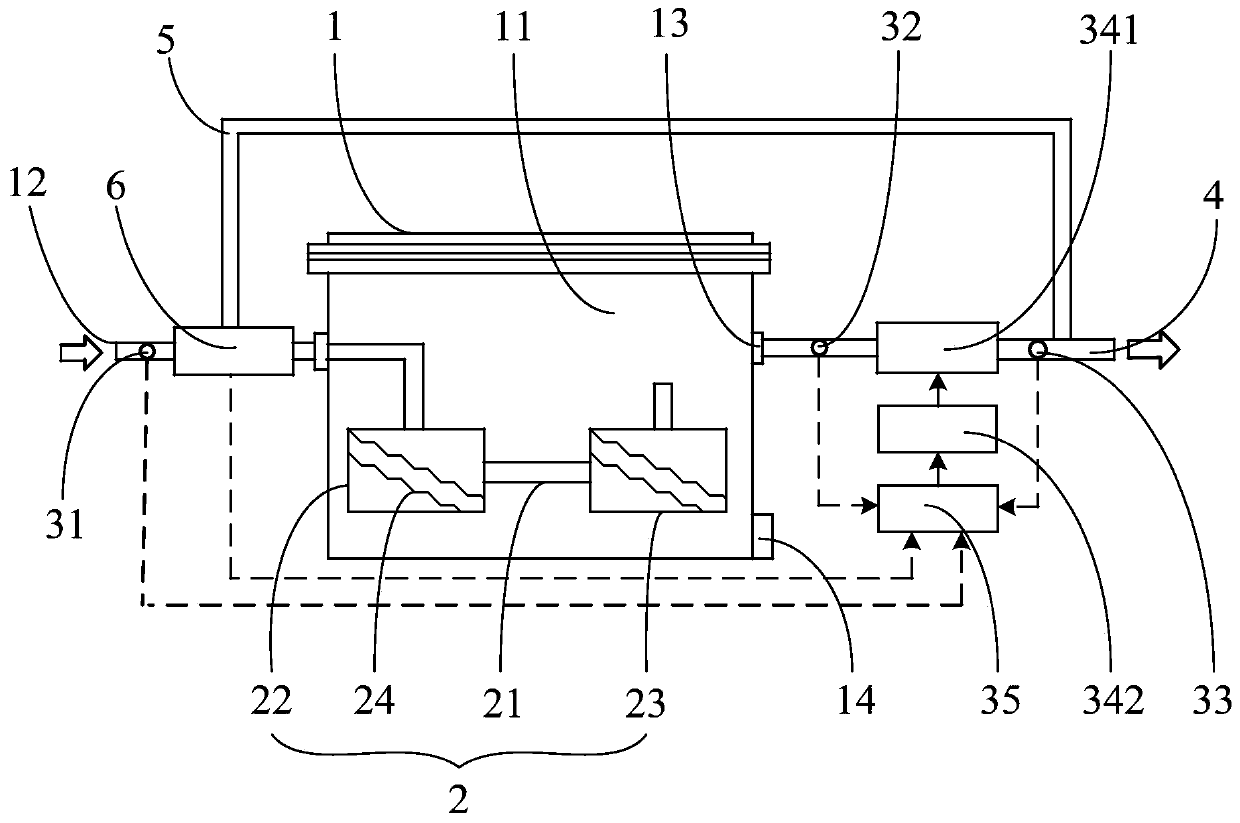
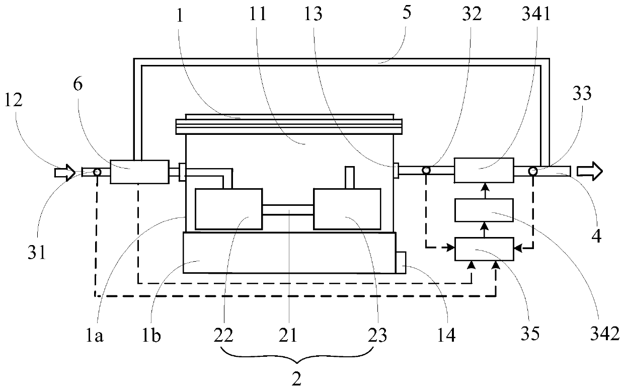
[0004] The main purpose of the present invention is to propose a device and method for measuring the amount of blow-by engine oil, aiming to solve the problems of poor separation effect and lower accuracy of measurement results in traditional engine oil blow-by measurement devices

Method used


Image

  • Device and method for measuring oil leakage amount of engine
  • Device and method for measuring oil leakage amount of engine

Examples


Embodiment Construction

[0040] The following will clearly and completely describe the technical solutions in the embodiments of the present invention with reference to the accompanying drawings in the embodiments of the present invention. Obviously, the described embodiments are only some of the embodiments of the present invention, not all of them. Based on the embodiments of the present invention, all other embodiments obtained by persons of ordinary skill in the art without creative efforts fall within the protection scope of the present invention.

[0041] It should be noted that if there is a directional indication (such as up, down, left, right, front, back...) in the embodiment of the present invention, the directional indication is only used to explain the position in a certain posture (as shown in the accompanying drawing). If the specific posture changes, the directional indication will also change accordingly.

[0042] In addition, if there are descriptions involving "first", "second" and ...


PUM


Abstract

The invention discloses a device and a method for measuring an oil leakage amount of an engine. The device for measuring the oil leakage amount of the engine comprises a device main body and a pressure compensation device, a cavity is formed in the device main body, a feed opening and a gas outlet are formed in the cavity, a filtering device is arranged in the cavity to enable gas liquid to enterfrom the feed opening, so that the gas liquid is separated into a gas and oil after being filtered by the filtering device, and the gas is output from the gas outlet; the pressure compensation deviceis disposed on the device main body for adjusting the pressure value of the device main body, such that an output pressure value of the device main body is equivalent to an input pressure value. In the device disclosed by the invention, the filtering device can optimize the separation effect of the gas and liquid, and helps to completely separate the oil in the gas liquid; the pressure compensation device helps to eliminate the problem of increased internal resistance of the cavity caused by the arrangement of the filtering device, and table circulation of the gas liquid can be ensured by adjusting the pressure balance in the cavity, so that a more accurate measurement result is obtained.

Description

technical field [0001] The invention relates to the technical field of engine detection, in particular to the technical field of engine oil blow-by detection, and in particular to a device and method for measuring engine oil blow-by. Background technique [0002] Generally, the engine will generate blow-by gas mixed with combustible mixture and exhaust gas during the working process. The blow-by gas will escape into the crankcase from the gap between the piston ring and the cylinder liner. If it is not treated in time, it will cause engine damage. The pressure in the crankcase gradually increases, eventually leading to engine oil seal failure, oil leakage and other problems; moreover, if the blow-by gas is directly discharged into the atmosphere, it will also cause air pollution. Therefore, in order to ensure the normal operation of the engine, the crankcase is generally equipped with a forced ventilation system, which will guide the blow-by gas to the combustion chamber for...

Claims


Application Information

Patent Timeline
Patent Type & Authority Applications(China)
IPC IPC(8): G01M15/02G01M15/04
CPCG01M15/02G01M15/04
Inventor 陈明虎梁敏臣梁程孙泽祝先标丁磊吴超薛龙龙
Owner ANHUI JIANGHUAI AUTOMOBILE GRP CORP LTD
Learn More