Core tube valve capable of achievingautomatic cutting duringbothway pipeline burst

A pipeline and core tube technology, which is applied in the sub-series of the conventional core tube valve plate, in the field of two-way pipeline burst self-cutting core tube valves, can solve the problems of uncontrollable resources, casualties, economic losses, pipeline resource loss and environmental damage, etc., to achieve Resource and life safety protection, improved reliability and safety, good inner sealing effect

Inactive Publication Date: 2019-10-11
卢星霖
View PDF9 Cites 0 Cited by
  • Summary
  • Abstract
  • Description
  • Claims
  • Application Information

AI Technical Summary

Problems solved by technology

[0002] At present, due to the structural characteristics of the existing valves, it is impossible to effectively solve the problems of resource loss and environmental damage caused by pipe bursts, especially the traffic problems, production problems, life problems and environmental problems caused by pipe bursts in tap water systems in cities all over the world. problem, a worldwide problem
The existing one-way pipeline burst control valve abroad can only control the upstream medium through the actuator and the energy system, and the resources in the downstream pipeline are still uncontrollable
Casualties and economic losses caused by bursting of high-temperature and high-pressure steam pipelines are also disastrous

Method used


Image

  • Core tube valve capable of achievingautomatic cutting duringbothway pipeline burst
  • Core tube valve capable of achievingautomatic cutting duringbothway pipeline burst
  • Core tube valve capable of achievingautomatic cutting duringbothway pipeline burst

Examples


Embodiment 1

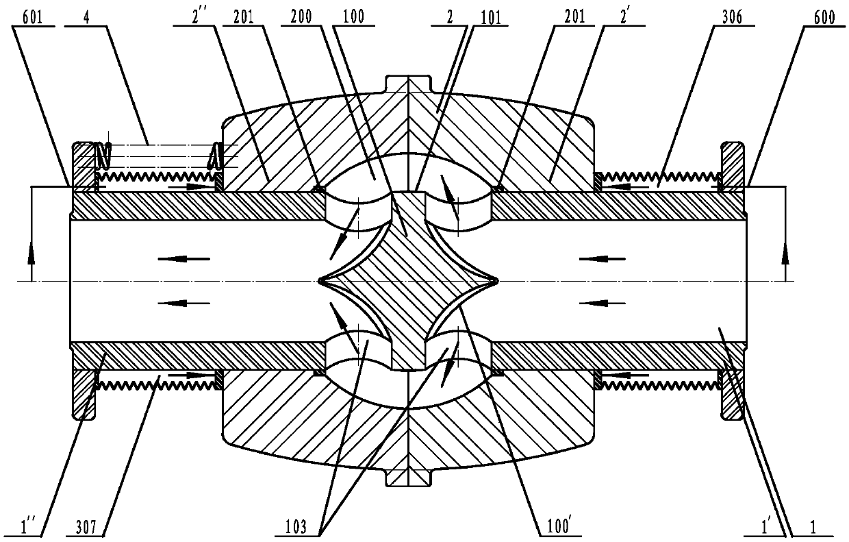
[0036] See attached figure 1 , 2 , 3, the two-way pipeline burst self-operated cut-off core tube valve described in this embodiment; the valve core tube 1 is the sleeve tube I2' that runs through the valve body 2 in the same axial direction as the fixing piece, the inner cavity 200 of the valve body 2, and the valve body 2’s sleeve pipe II 2″; there is an axial partition 100 in the middle of the spool tube 1, the interlayer 100 is composed of the inner core and the middle section of the spool tube 1 radially radiating from the inner core, and the two axial end faces of the inner core of the interlayer 100 are tongues triangular slope surface 100′; the axially adjacent two sides of the interlayer 100 are respectively two radial flow holes 103 of the input section 1′ and the output section 1″; ' and the annular valve seat 201 at the throat of the sleeve tube II2" all constitute a sealing pair; the input section 1' and the sleeve tube I2' and the output section 1" and the sleeve...

Embodiment 2

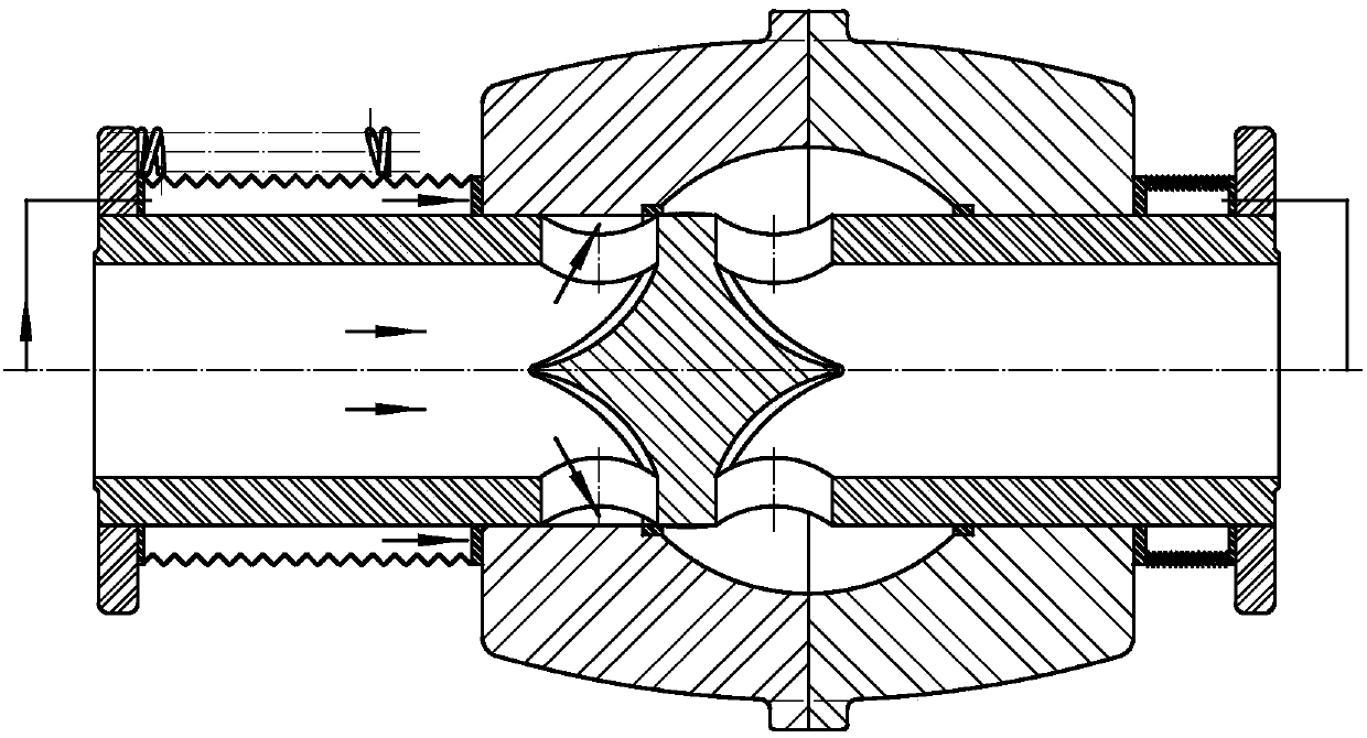
[0041] See attached Figure 4 , 5 6. The bidirectional pipe burst self-cutting core tube valve described in the embodiment; the valve core tube 1 is a sleeve tube I2' coaxially penetrating through the valve body 2, the inner cavity 200 of the valve body 2, and the valve body 2. Sleeve II 2″; there is an axial partition 100 in the middle of the valve core tube 1, and the partition 100 is composed of the inner core and the middle section of the core tube 1 radially radiating from the inner core, and the two axial end faces of the core tube 100 are tongue-shaped The triangular slope surface 100'; the axially adjacent two sides of the interlayer 100 are respectively the two radial flow holes 103 of the input section 1' and the output section 1"; the sealing surface of the annular valve core 101 surrounding and embedded in the interlayer 100 is bidirectional The slope surface and the annular valve seat 201 at the throat of the sleeve tube I2' and the sleeve tube II2" all constitut...

Embodiment 3

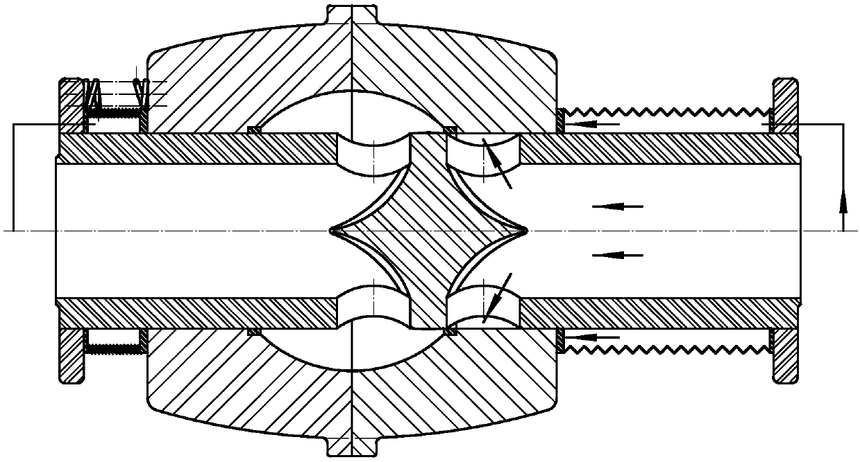
[0046] See attached Figure 7 , 8 , 9, the two-way pipe burst self-cutting core tube valve described in this embodiment; the valve core tube 1 is a sleeve tube I2' that runs through the valve body 2 in the same axial direction as the fixing piece, the inner cavity 200 of the valve body 2, and the valve body 2’s sleeve tube II 2″; there is an axial partition 100 in the middle of the spool tube 1, the interlayer 100 is composed of the inner core and the middle section of the spool tube 1 radially radiating from the inner core, and the two axial end faces of the inner core of the interlayer 100 are spherical surfaces ; The axially adjacent two sides of the interlayer 100 are respectively the four radial flow holes 103 of the input section 1' and the output section 1 "; The annular valve seat 201 at the top constitutes a sealing pair; bellows seals 300 are provided at the joints of the input section 1' and the sleeve I2' and the output section 1" and the sleeve II2"; a hydraulic ...


PUM


Abstract

The invention discloses a core tube valve capable of achieving automatic cutting duringbothway pipeline burst. The core tube valve is a sub series of conventional core tube valve plate blocks in the original core tube valve mother series. The valve core tube is a fixed part which coaxially penetrates through a sleeve tube I of a valve body, an inner cavity of the valve body and a sleeve tube II ofthe valve body; an axial partition layer is arranged on the middle part of the valve core tube; two axial adjacent sides of the partition layer are separately equipped with at least one radial circulating hole of an input section and an output section; a ring-shaped valve element which surrounds the partition layer and a ring-shaped valve seat on the throat part of the sleeve tube I and the throat part of the sleeve tube II define a sealing pair; the input section and the sleeve tube I are in shaft hole type fit, and the output section and the sleeve tube II are in shaft hole type fit; a pressure element is arranged between the input section and the end part of the sleeve tube I, aninner cavity of the pressure element communicates with front pressure of the valve through a channel; a pressure element is arranged between the output section and the end part of the sleeve tube II, and aninner cavity of the pressure element communicates with back pressure of the valve through a channel; and when a pipeline in any direction is burst, the valve body instantaneously moves axially to cut off medium flow. The core tube valve is simple in structure, is flexible in opening and closing, is safe and reliable, and protects resource, life and environment.

Description

technical field [0001] The two-way pipe burst self-cutting core pipe valve of the present invention belongs to the field of valves, and is a sub-series of the conventional core pipe valve plate in the core pipe valve mother series invented by myself. Background technique [0002] At present, due to the structural characteristics of the existing valves, it is impossible to effectively solve the problems of resource loss and environmental damage caused by pipe bursts, especially the traffic problems, production problems, life problems and environmental problems caused by pipe bursts in tap water systems in cities all over the world. The problem is a worldwide problem. The existing one-way pipeline burst control valve abroad can only control the upstream medium through the actuator and energy system, and the resources in the downstream pipeline are still uncontrollable. Casualties and economic losses caused by bursting of high-temperature and high-pressure steam pipelines are ...

Claims


Application Information

Patent Timeline
Patent Type & Authority Applications(China)
IPC IPC(8): F16K17/04
CPCF16K17/044
Inventor 卢星霖
Owner 卢星霖
Why Eureka
Try Eureka