
Lifting supporting type elevator shaft formwork device and construction method

An elevator shaft and supporting technology, which is applied in the fields of formwork/formwork/work frame, formwork processing, and on-site preparation of building components, can solve the safety risk of workers falling from drilling holes, damage to the support strength of the wall, and lack of Protection and other issues, to avoid the risk of falling objects, shorten the construction period, efficient and labor-saving and easy demoulding effect

Active Publication Date: 2019-10-11
NO 9 METALLURGICAL CONSTR
View PDF12 Cites 9 Cited by
  • Summary
  • Abstract
  • Description
  • Claims
  • Application Information

AI Technical Summary

Problems solved by technology

[0004] The technical problem solved by the present invention is to provide a hoisting and supporting formwork device for an elevator shaft. By thoroughly improving the formwork assembly in the well and the lifting method of the formwork in the well, it is solved that the formwork in the elevator well in the prior art must be drilled in the forming wall. The technical problem affecting the support strength of the damaged wall; and through the improved well formwork assembly, solve the technical problem of lack of protection for workers' drilling and well formwork construction, and the high safety risk of workers' drilling and falling; and by improving the layout of the demoulding mechanism And the structure solves the technical problem that the demoulding mechanism in the prior art tends to cause the template to deform due to inclined pulling and demoulding

Method used


Image

  • Lifting supporting type elevator shaft formwork device and construction method
  • Lifting supporting type elevator shaft formwork device and construction method
  • Lifting supporting type elevator shaft formwork device and construction method

Examples


Embodiment Construction

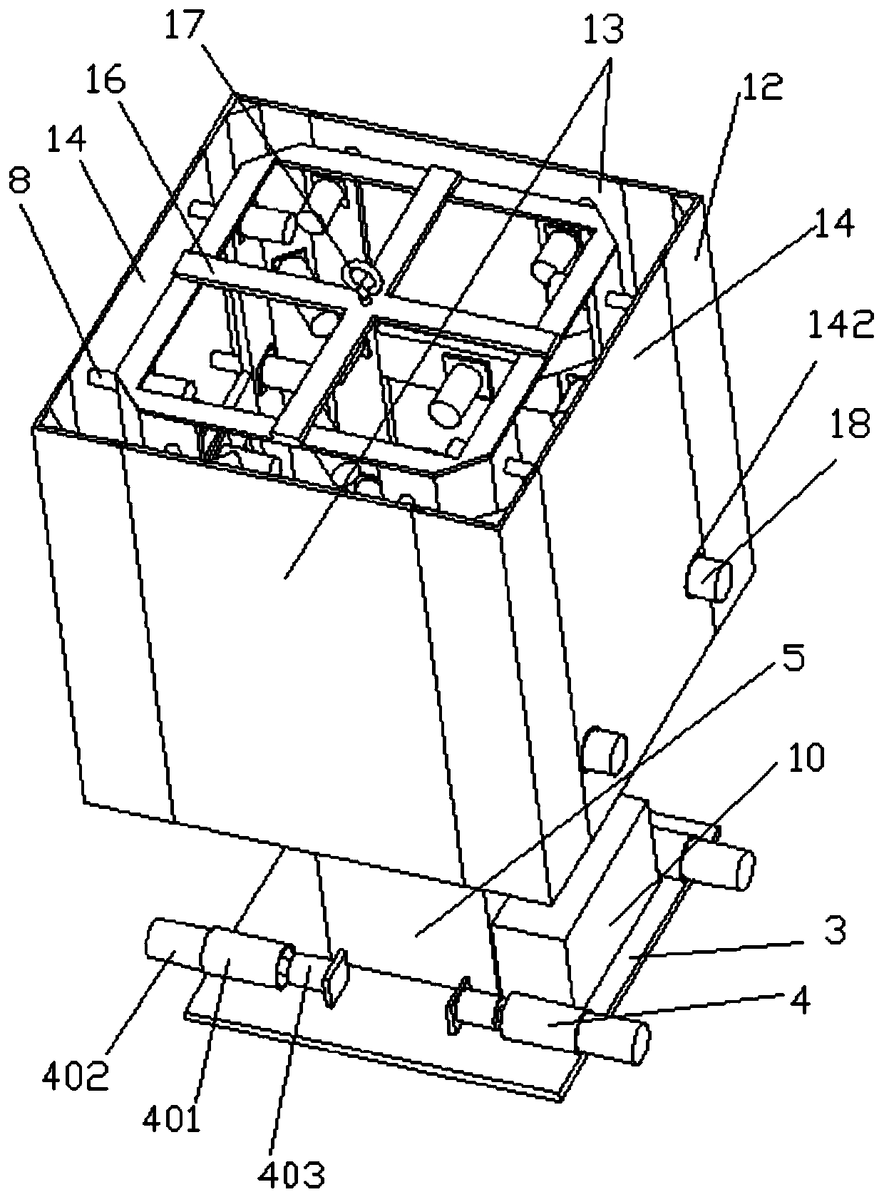
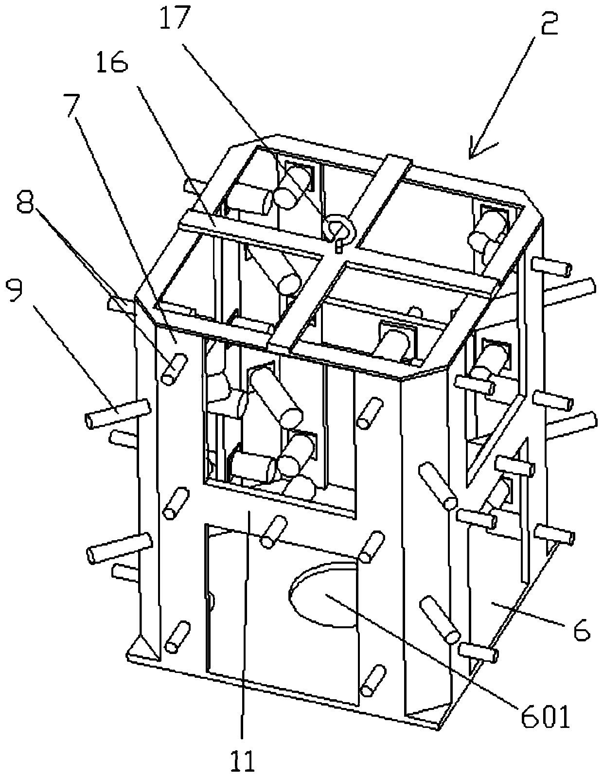
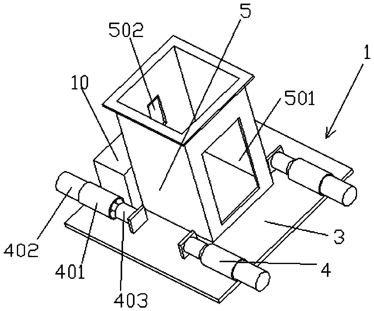
[0033] Attached below Figure 1-7 Specific examples of the present invention are described.

[0034] The following examples facilitate a better understanding of the present invention, but do not limit the present invention. The hoisting methods and the construction of the formwork outside the well in the following embodiments are all conventional hoisting methods and construction methods without special instructions. The names of parts and parts materials used in the following examples are commercially available unless otherwise specified. In the following embodiments, the realization of the control circuit where the control box is electrically connected to the hydraulic cylinder is a conventional control method unless otherwise specified; the connection between the hydraulic cylinder and the hydraulic circuit before the hydraulic station is a conventional hydraulic control method unless otherwise specified. Loop connection method.

[0035] In the present invention, unless ...


PUM


Abstract

The invention provides a lifting supporting type elevator shaft formwork device. A bottom supporting start device comprises a rectangular bottom plate, a rectangular barrel, a hydraulic station, a control box and a positioning supporting assembly. An elevator shaft formwork assembly is provided with a rectangular platform plate, vertical folding plates, a rectangular connecting plate, a rectangular connecting frame, a cross-shaped supporting frame and a lifting hook. Multiple horizontally-arranged hydraulic cylinders are further arranged. The execution ends of the hydraulic cylinders are vertically hinged to a rectangular downhole formwork formed by two front and rear first planar formworks, two left and right second planar formworks and four right-angle formworks. Through the combinationof the bottom supporting start device and the elevator shaft formwork assembly, the formworks in an elevator shaft are conveniently laid, a protective platform is formed in the elevator shaft, throughlifting of a tower crane, the above elevator shaft continues to be supported through inserted connection of the positioning supporting assembly and a drum body for facilitating formwork erecting, andthe technical problems that formwork erecting in an existing elevator shaft is inconvenient and not safe, and the formworks are prone to deform during formwork removal are solved.

Description

technical field [0001] The invention belongs to the technical field of construction formwork for elevator shafts of fixed buildings, and in particular relates to a hoisting and supporting elevator shaft formwork device and a construction method. Background technique [0002] Aluminum formwork, the full name of aluminum alloy formwork system for construction, is a new generation of new formwork support system after bamboo formwork and steel formwork. When using aluminum formwork to form the elevator shaft, it needs to be poured layer by layer. Under the existing technology, when pouring the elevator shaft layer by layer, it is necessary to build the outer formwork first, then build the inner formwork inside the outer formwork, and finally fix the top formwork, and then pour cement into the built formwork system to form a layer of elevator shaft . However, when the outer formwork of the new layer is completed and the inner formwork of the previous layer needs to be built, it...

Claims


Application Information

Patent Timeline
IPC IPC(8): E04G11/20E04G11/28E04G19/00
CPCE04G11/20E04G11/28E04G19/00
Inventor 楚继德闫立升范权德张少龙谢田军
Owner NO 9 METALLURGICAL CONSTR
Learn More