Constant-flow-rate water drainage control method and control system
A control method and control system technology, applied in the field of constant flow drainage control method and control system, can solve the problems of control lag and low control precision, and achieve the effects of precise control, fast response speed and high reliability
- Summary
- Abstract
- Description
- Claims
- Application Information
AI Technical Summary
Problems solved by technology
Method used
Image
Examples
Embodiment 1
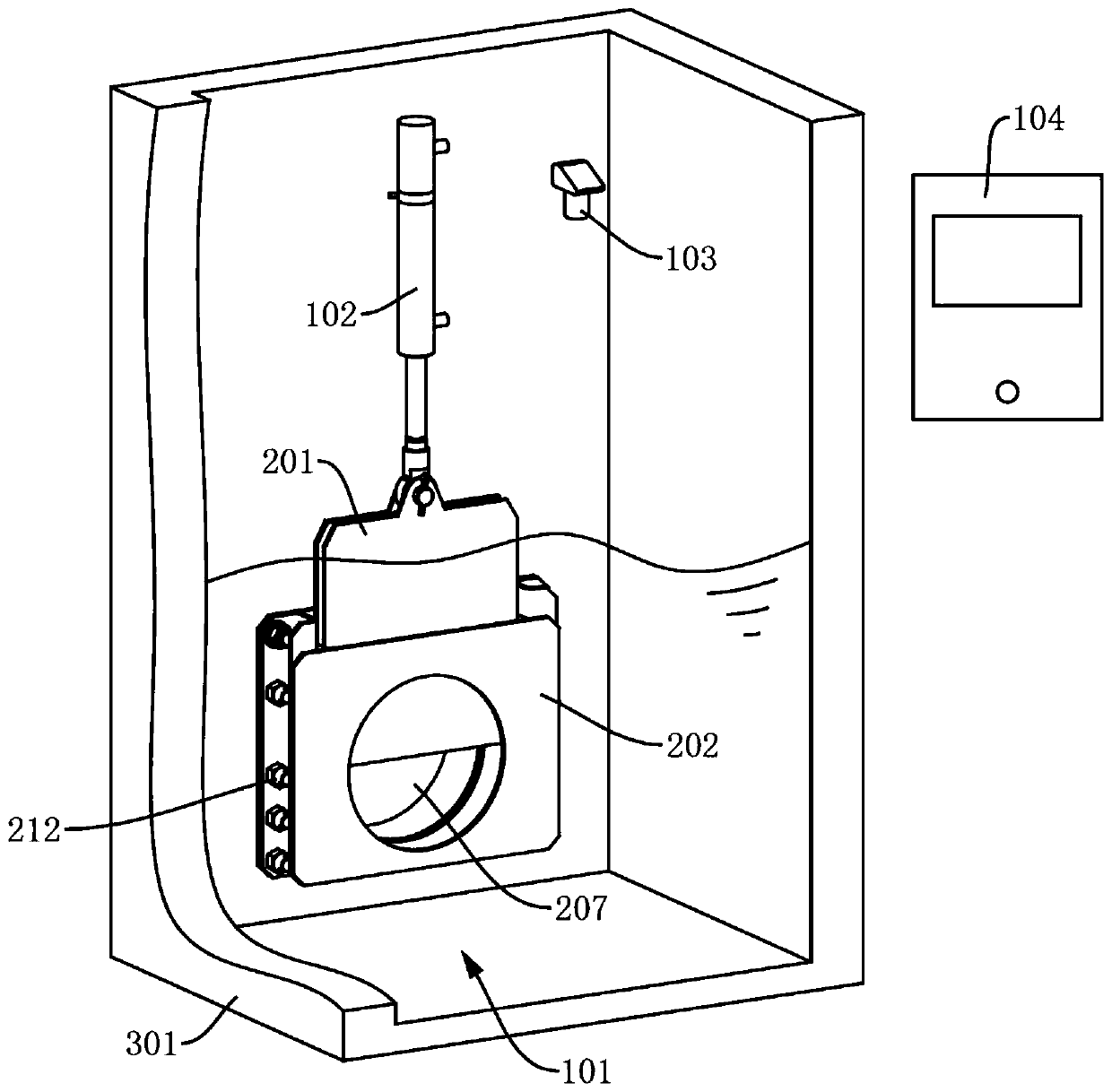
[0051] see figure 1 , the present embodiment provides a constant flow drainage control method, including step 1, monitoring the liquid level height at the opening and closing gate 101, and obtaining liquid level height data; step 2, according to the set drainage flow rate and the described Calculate the theoretical flow area corresponding to the liquid level data; step 3, adjust the opening of the opening and closing gate 101 so that the real-time flow area of the opening and closing gate 101 is equal to the theoretical flow area. As for the opening and closing gate 101, there is a definite corresponding relationship between the opening of the opening and closing gate 101 and the real-time flow area of the opening and closing gate 101, and according to the knowledge of hydraulics, it can be known that a water passage hole 207 under water There is a definite corresponding relationship between the drainage flow rate at the water hole 207 and the flow area of the water hole...
Embodiment 2
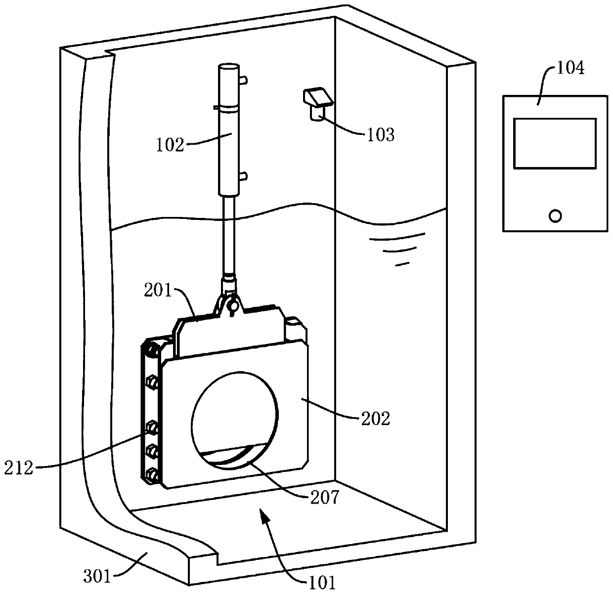
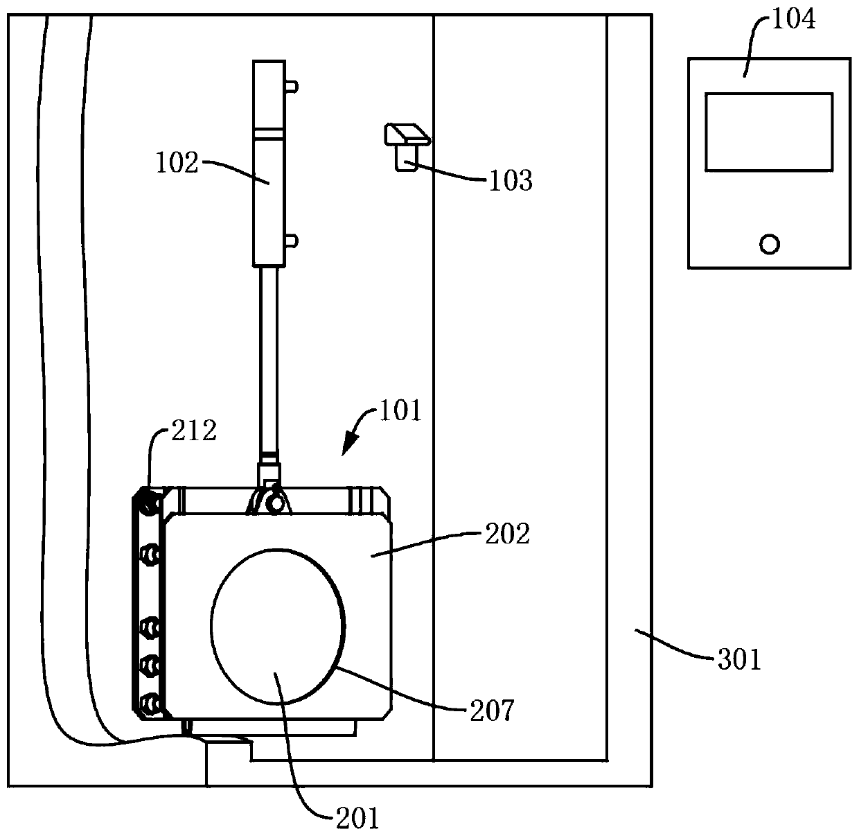
[0061] According to the above method, this embodiment provides a constant flow drainage control system, including the opening and closing gate 101 installed at the drain, the driving part 102 for adjusting the opening of the opening and closing gate 101, and the control system for monitoring the liquid level. The liquid level sensor 103, and the controller 104 connected to the drive unit 102 and the liquid level sensor 103 respectively, the controller 104 is used to obtain the liquid level height data collected by the liquid level sensor 103, and according to the set Drainage flow and the height data of the liquid level control the drive unit 102 to adjust the opening of the opening and closing gate 101, as figure 1 , figure 2 and image 3 shown. Because for the opening and closing gate 101, there is a definite correspondence between the opening of the opening and closing gate 101 and the real-time flow area of the opening and closing gate 101 (that is, when the opening o...
Embodiment 3
[0078] According to the method provided in Embodiment 1, this embodiment provides a way for the controller 104 to achieve precise control in the constant flow drainage control system described in Embodiment 2:
[0079] In this embodiment, the driving unit 102 is a hydraulic cylinder, and the controller 104 stores the above calculation formula and the corresponding relationship between k and h (different according to the shape of the water hole 207).
[0080] When the liquid level sensor 103 detects that the current liquid level height is H 1 , according to the formula and S 1 =k 1 h 1 ,Available:
[0081]
[0082] Among them, S 1 is the current flow area;
[0083] When the liquid level sensor 103 detects that the current liquid level height is H 2 , it can be concluded that:
[0084]
[0085] Since the flow rate needs to be controlled constant, that is, Q 1 =Q 2 , then there are:
[0086]
[0087] Organized to get:
[0088]
[0089] where k 1 、k 2 , ...
PUM
 Abstract
Description
Claims
Application Information
 - Generate Ideas
- Intellectual Property
- Life Sciences
- Materials
- Tech Scout
- Unparalleled Data Quality
- Higher Quality Content
- 60% Fewer Hallucinations
Browse by: Latest US Patents, China's latest patents, Technical Efficacy Thesaurus, Application Domain, Technology Topic, Popular Technical Reports.
© 2025 PatSnap. All rights reserved.Legal|Privacy policy|Modern Slavery Act Transparency Statement|Sitemap|About US| Contact US: help@patsnap.com


