Electromagnetic valve and air conditioning system

A solenoid valve, moving iron core technology, applied in the direction of lift valve, valve details, valve device, etc., can solve the problems of large flow resistance, large pressure loss, short stroke, etc., to reduce pressure loss, increase distance, reduce The effect of flow resistance

Inactive Publication Date: 2019-10-08
ZHEJIANG DUNAN MASCH CO LTD
View PDF5 Cites 0 Cited by
  • Summary
  • Abstract
  • Description
  • Claims
  • Application Information

AI Technical Summary

Problems solved by technology

[0002] At present, the core iron in the solenoid valve is composed of a static iron core and a moving iron core, and its stroke is relatively short, generally within 2mm, resulting in a large flow resistance and a large pressure loss after being fully opened.

Method used


Image

  • Electromagnetic valve and air conditioning system
  • Electromagnetic valve and air conditioning system
  • Electromagnetic valve and air conditioning system

Examples


Embodiment 1

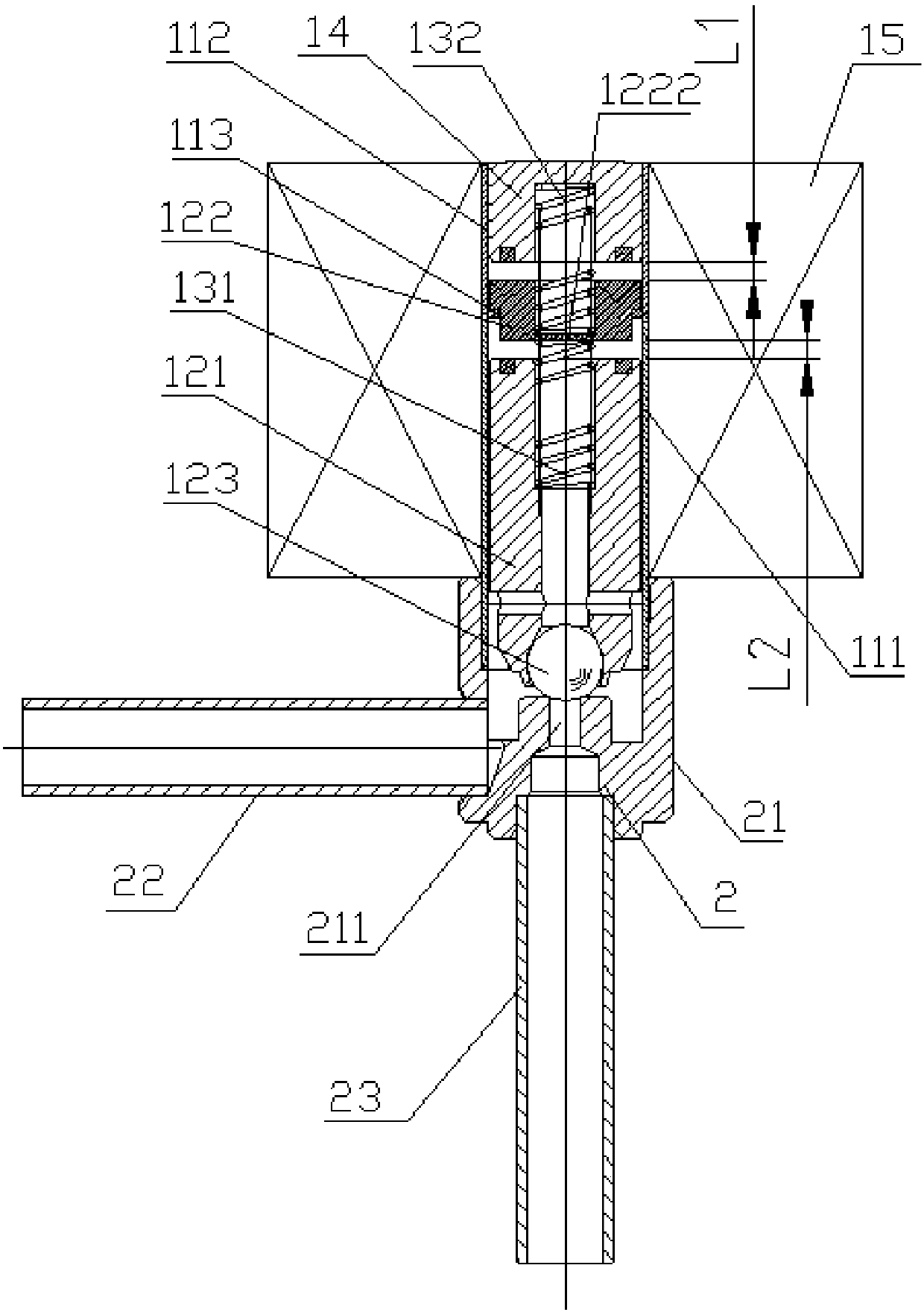
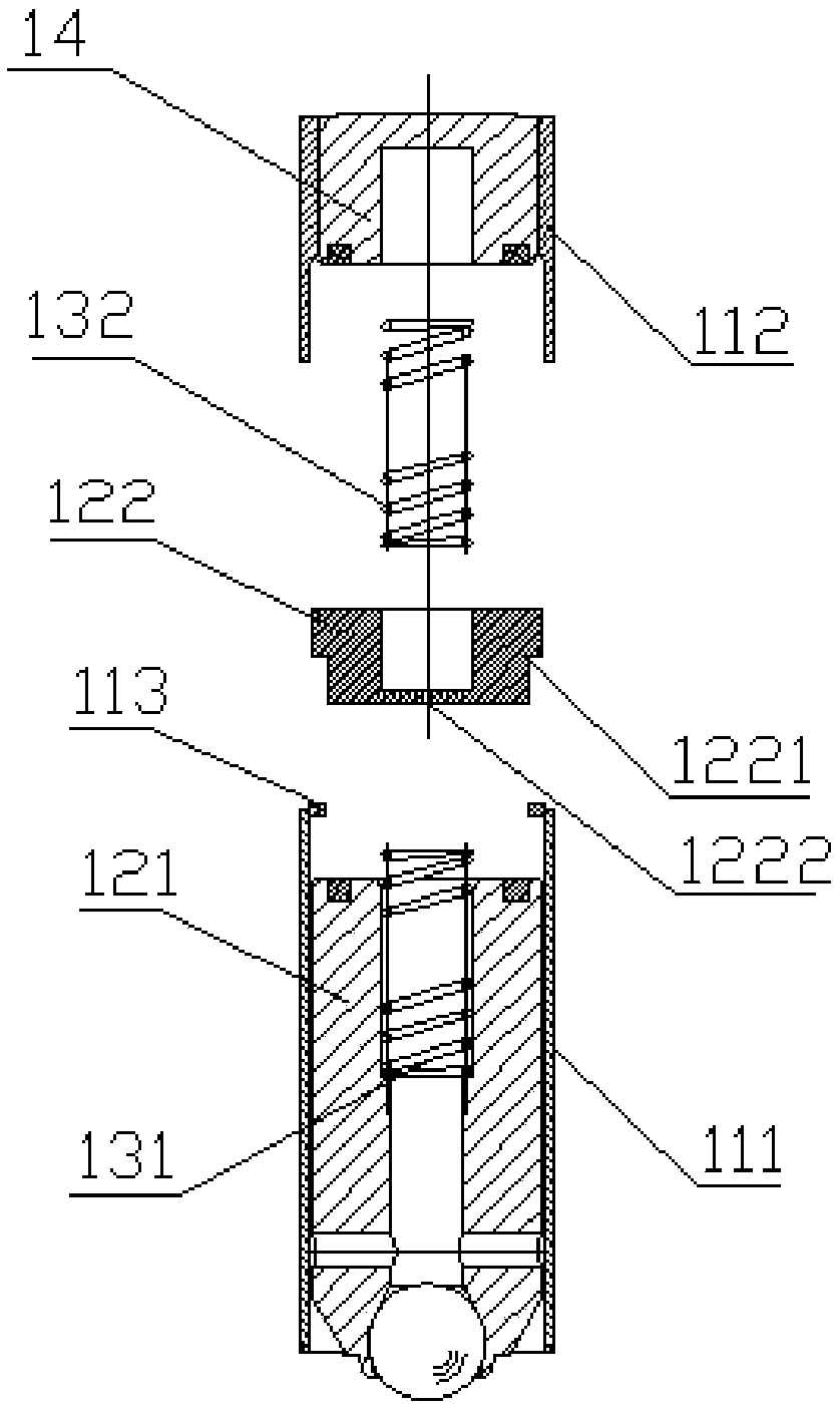
[0030] Embodiment one, such as figure 1 with figure 2 As shown, a solenoid valve includes a valve body part 2 and an electromagnetic control part 1, wherein the valve body part 2 includes a valve body 21 with a first interface and a second interface, the first interface is connected to the first connecting pipe 22, and the second The interface is connected to the second connecting pipe 23 , and the valve body 21 is provided with a valve port 211 communicating with the second interface. The electromagnetic control part 1 includes a casing, a coil 15 arranged outside the casing, a static iron core 14 installed at the rear end of the casing, and a moving iron core arranged in the casing, and the moving iron core includes a first moving iron core arranged separately. An iron core 121 and a second moving iron core 122, the first moving iron core 121 is located in front of the second moving iron core 122 and a first return spring 131 is arranged between the first moving iron core ...

Embodiment 2

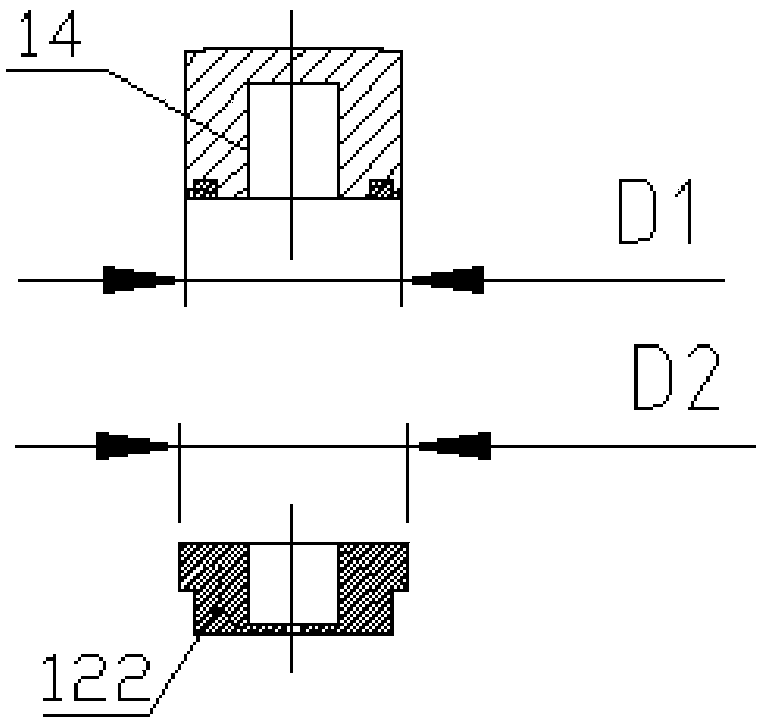
[0036] Embodiment 2, on the basis of Embodiment 1, in order to further ensure that the first moving iron core 121 and the second moving iron core 122 are attracted first when the coil 15 is energized, and then the second moving iron core 122 is connected with the first moving iron core 121 Together with the static iron core 14 suction, and to avoid malfunction. It can be set in such a way that the suction force between the first moving iron core 121 and the second moving iron core 122 is greater than the suction force between the second moving iron core 122 and the static iron core 14 when the coil 15 is energized.

[0037] refer to figure 1 As shown, when the coil 15 is powered off, the first moving iron core 121 , the second moving iron core 122 and the static iron core 14 are separated by the first return spring 131 and the second return spring 132 . Wherein, the distance between the second moving iron core 122 and the static iron core 14 is L1, the distance between the fi...

Embodiment 3

[0043] Embodiment 3, an air conditioning system is provided with the above-mentioned solenoid valve.


PUM


Abstract

The invention discloses an electromagnetic valve and an air conditioning system. The electromagnetic valve comprises a sleeve, a coil arranged outside the sleeve, a static iron core arranged at the rear end of the sleeve, and a movable iron core arranged in the sleeve; and the movable iron core comprises a first movable iron core and a second movable iron core which are arranged in a split mode, the first movable iron core is located in front of the second movable iron core, a first returning spring is arranged between the first movable iron core and the second movable iron core, a second returning spring is arranged between the second movable iron core and the static iron core, and a damping hole for enhancing the attraction resistance between the second movable iron core and the static iron core is formed in the second movable iron core. According to the electromagnetic valve, the movable iron core is divided into the first movable iron core and the second movable iron core which arearranged in a two-section mode, and meanwhile, the damping hole for enhancing the attraction resistance between the second movable iron core and the static iron core is formed in the second movable iron core so as to ensure that the first movable iron core and the second movable iron core are attracted together firstly when the coil is electrified, and then the second movable iron core and the first movable iron core are jointly attracted to the static iron core to be a whole.

Description

technical field [0001] The invention relates to the technical field of air conditioning. Background technique [0002] At present, the core iron in the solenoid valve is composed of a static iron core and a moving iron core, and its stroke is relatively short, generally within 2mm, resulting in a large flow resistance and a large pressure loss after being fully opened. Contents of the invention [0003] The technical problem to be solved by the present invention is to provide a solenoid valve, which increases the stroke and reduces the flow resistance and pressure loss. [0004] In order to solve the above-mentioned technical problems, the present invention adopts the following technical solutions: a solenoid valve, comprising a casing, a coil arranged outside the casing, a static iron core installed at the rear end of the casing, and a moving iron core arranged inside the casing. The moving iron core includes a first moving iron core and a second moving iron core arrange...

Claims


Application Information

Patent Timeline
Patent Type & Authority Applications(China)
IPC IPC(8): F16K31/06F16K1/36
CPCF16K1/36F16K31/0665F16K31/0675F16K31/0696
Inventor 胡煜刚朱龙健侯晓炜
Owner ZHEJIANG DUNAN MASCH CO LTD
Why Eureka
Try Eureka